4-17
4.1.11. Magnetron fan replacement / NKE-2254
[Required tools]
• A Phillips screwdriver for 4 mm screws
• A Phillips screwdriver for 5 mm screws
• Tools for removing the scanner unit covers (See Section 4.1.2)
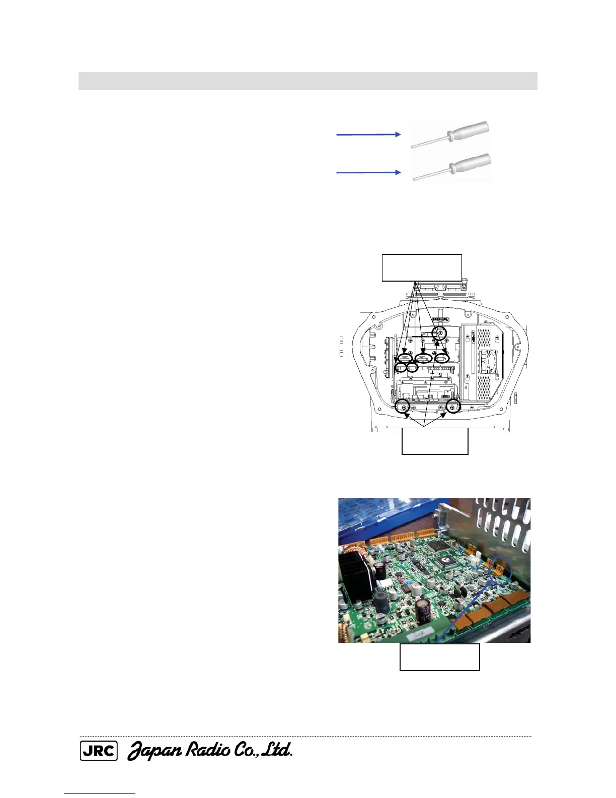
(1) Remove the cover on the right (starboard)
side (see Section 4.1.2), remove the cables
connected to the transmitter-receiver unit
and the screws (three M5 screws) holding
the transmitter-receiver unit in place, and
remove the transmitter-receiver unit.
(2) Remove the cable for the fan that is
connected to the T/R control circuit board.
Remove the five
cables.
Remove the
three screws.
Remove the
cable.

 Loading...


