4-28
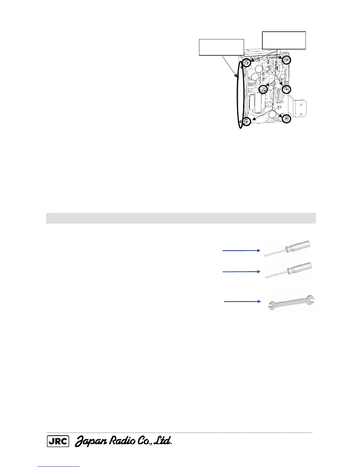
(3) Remove the six M4 screws and two M3
screws, and detach the power circuit from
the mounting plate.
(4) After the power circuit replacement, carry out the work in reverse order of removal.
Be sure to tighten all the bolts and screws and connect all the cables.
If the square radiating sheet attached to the chassis on the back (solder side) of
the power circuit is torn, change to a new one provided with the replacement power
circuit.
4.1.19. Receiver (NRG-610) Replacement for the NKE-2103
[Required tools]
• A Phillips screwdriver for 4 mm screws
• A Phillips screwdriver for 5 mm screws
• A single-ended wrench (width across flats 7 mm for M4 bolts)
• Tools for removing the scanner unit covers (See Section 4.1.2.)
[Replacement procedure]
(1) Open the top cover (see Section 4.1.2),
and remove the transmitter-receiver unit
(see Section 4.1.6). After that, remove
the magnetron (see Section 4.1.6).
Remove the six
screws (M4).
Remove the two
screws

 Loading...


