4-29
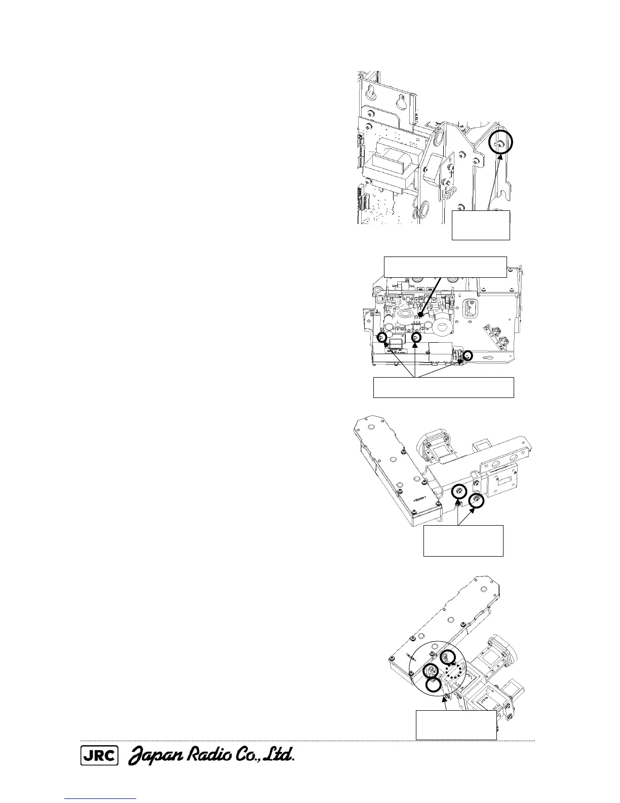
(2) Remove the 3D circuit and receiver from
the transmitter-receiver unit according to
the procedure below.
(a) Remove the M4 screw near the
magnetron.
(b) Remove the three screws (M4) from
the motor control power circuit, and
remove the 3D circuit from the
chassis.
(c) Remove the two screws (M4) that
secure the 3D circuit, and detach the
3D circuit from the mounting plate.
(d) Remove the four screws (M4) that
secure the receiver, and replace it.
Remove the
M4 screw.
Remove the two
screws (M4).
Remove the four
screws (M4).
Motor control power circuit
Remove the three screws (M4).

 Loading...


