4-27
[Operation check]
After completing the replacement work, check the operation by following the
procedure below.
(1) Turn on the radar, transmit radar signals when the countdown is finished, and
check that radar images are displayed normally.
After long range transmission, open the service engineer menu, and confirm that
the magnetron current indicator shows 50 to 70%.
4.1.18. Power Circuit (CBD-1783) Replacement for the NKE-2103
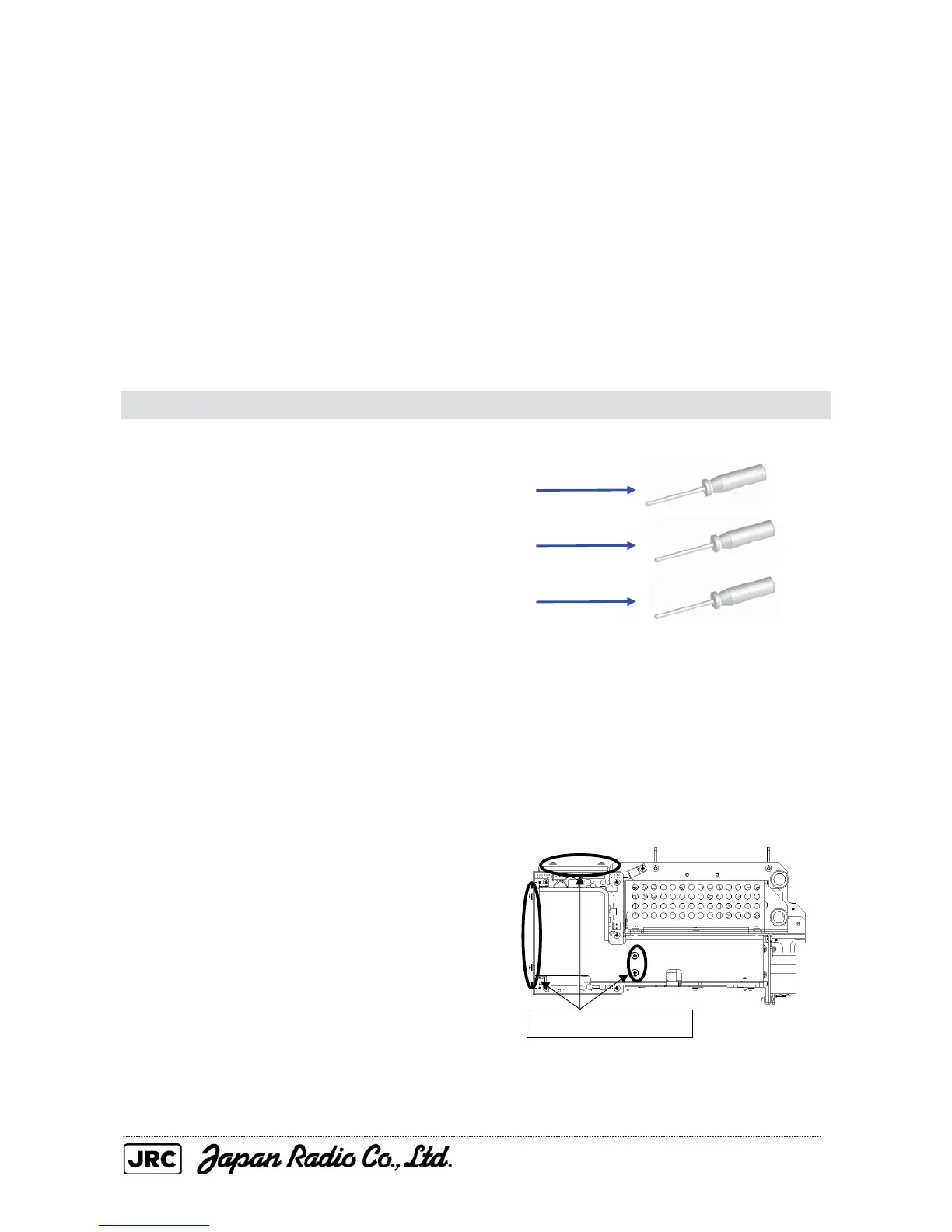
[Required tools]
• A Phillips screwdriver for 3 mm screws
• A Phillips screwdriver for 4 mm screws
• A Phillips screwdriver for 5 mm screws
• Tools for removing the scanner unit covers (See Section 4.1.2.)
[Replacement procedure]
(1) Open the top cover (see Section 4.1.2),
and remove the transmitter-receiver unit
(see Section 4.1.6).
(2) Disconnect the cables and remove the six
screws (M4) from the power circuit, and
then remove the power supply unit from the
transmitter-receiver unit.
Remove the six screws.

 Loading...


