4-2
4.1.2. Parts Replacement for the Scanner Unit NKE-2254
[Required tools]
• Tools for removing the cover from the scanner unit
A wrench (width across flats 13 mm for M8 bolts)
• Tools used in each part replacement procedure
[Replacement procedure]
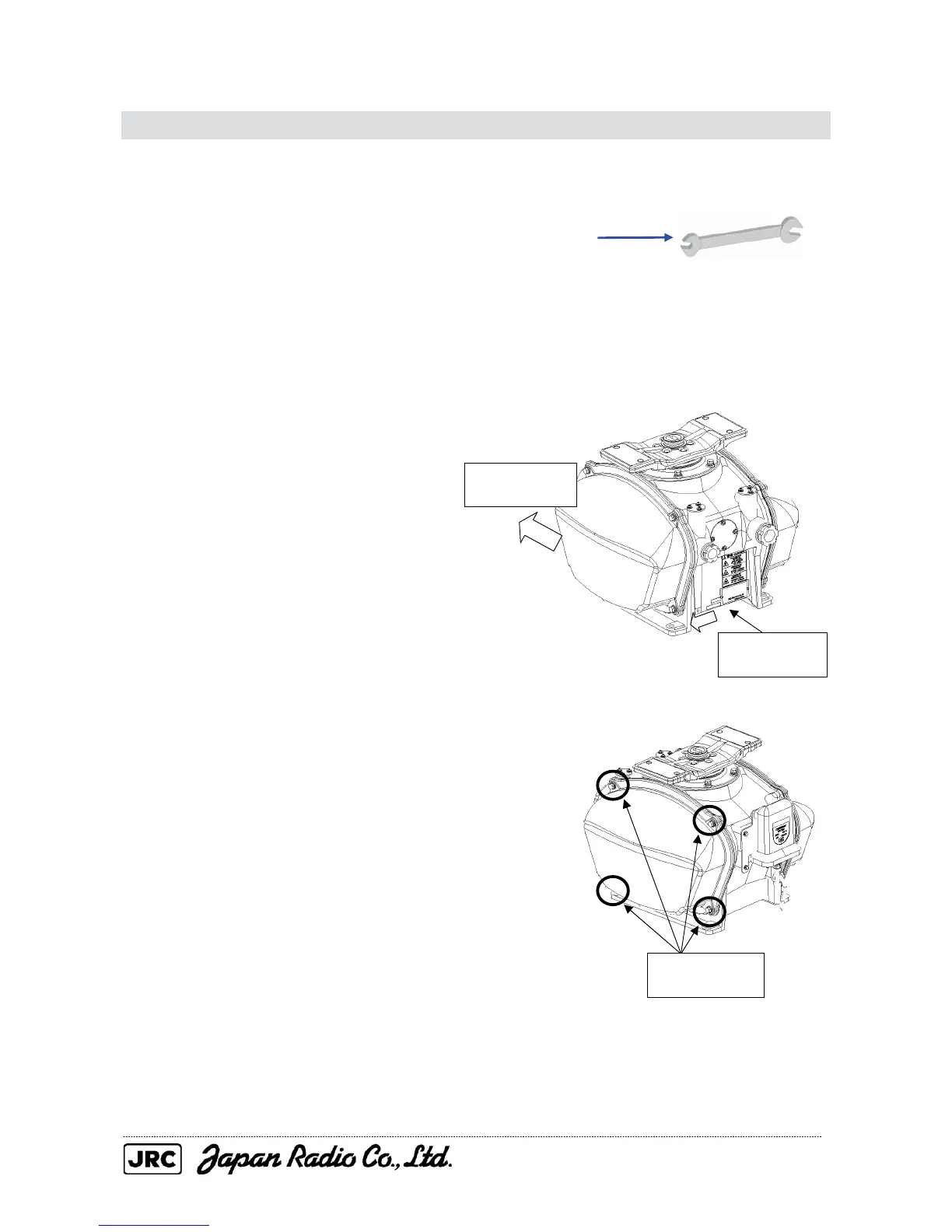
(1) Before starting the work, turn off the
safety switch at the bottom of the scanner
unit.
(2) Loosen the four hexagon bolts, and
remove the pedestal cover.
To replace the following parts, remove
the cover from the left (port) side:
• Motor
• Motor driver circuit
To replace the following parts, remove
the cover from the right (starboard) side:
• Transmitter (magnetron, modulation
circuit, or fan for the modulation circuit)
• Receiver
• T/R control circuit
• Power circuit
• Encoder
Ship's heading
bearing
Set the safety
switch to OFF.
Ship's heading
bearing
Loosen the four
hexagon bolts.

 Loading...


