4-3
(3) Replace the parts, which need replacement, according to the procedures in the
subsequent sections.
Be careful not to lose screws or brackets removed during replacement.
(4) After the parts replacement, mount the pedestal cover, set the safety switch to ON.
(Be sure to cap the safety switch.)
The packing shall be clean, free from dust and dirt when you mount the cover.
(5) Turn on the radar, and perform necessary operation checks.
4.1.3. Magnetron replacement / NKE-2254
[Required tools]
• A Phillips screwdriver for 4 mm screws
• A Phillips screwdriver for 5 mm screws
• Tools for removing the scanner unit covers (See Section 4.1.2.)
[Replacement procedure]
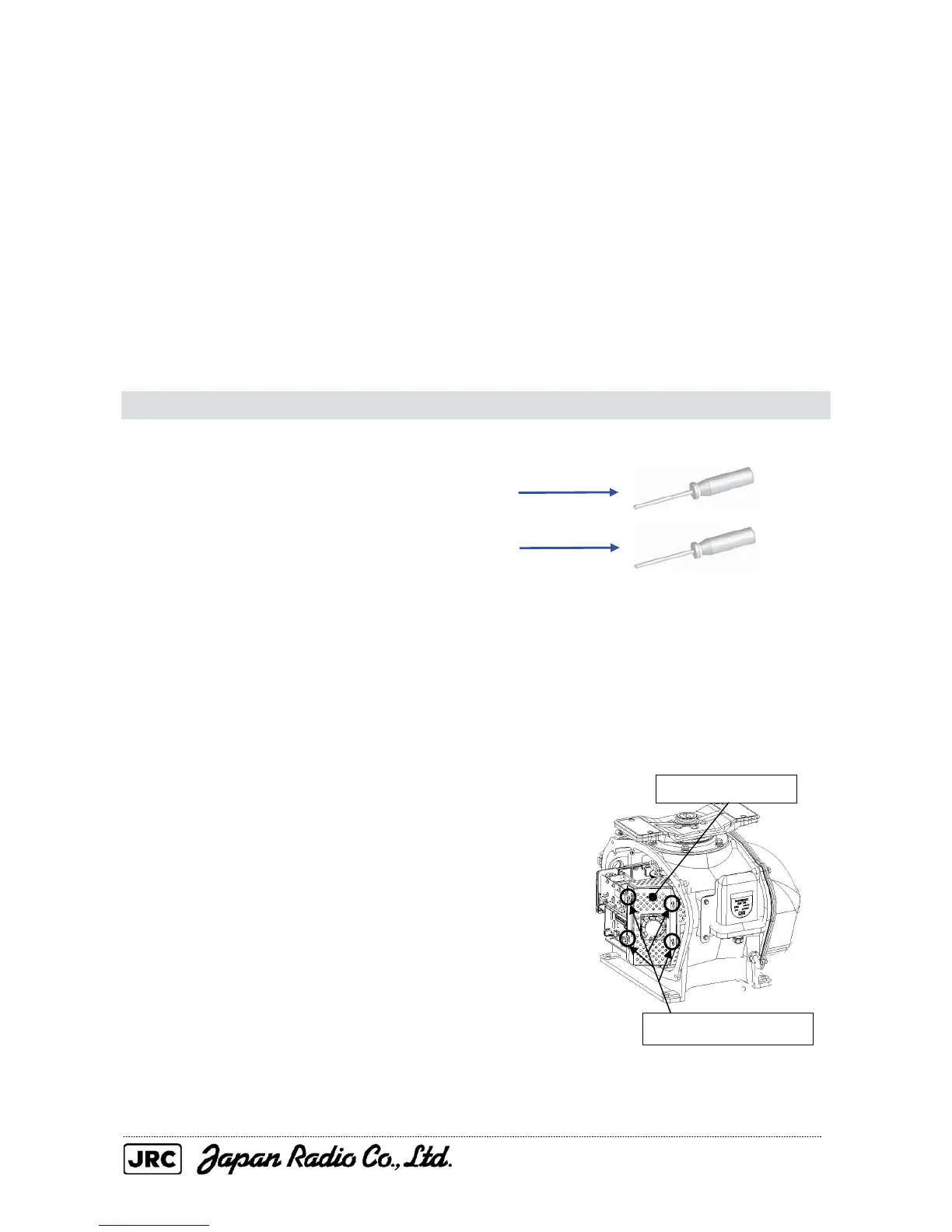
(1) Remove the covers from the right (starboard) side (see Section 4.1.2) and loosen
the screws (four M4 screws) to remove the magnetron cover.
Loosen the four screws.
Magnetron cover

 Loading...


