4-30
(3) After the receiver replacement, carry out
the work in reverse order of removal.
Be sure to tighten all the bolts and
screws and connect all the cables.
After receiver replacement, perform the assembly procedure, paying attention
to the fitting of the transmitter-receiver unit. If the fitting is poor, loosen the
screws and perform the adjustment again.
4.1.20. Encoder Replacement for the NKE-2103
[Required tools]
• A Phillips screwdriver for 4 mm screws
• A Phillips screwdriver for 5 mm screws
• A single-ended wrench (width across flats 7 mm for M4 bolts)
• Tools for removing the scanner unit covers (See Section 4.1.2.)
[Replacement procedure]
(1) Open the top cover (see Section 4.1.2),
and remove the transmitter-receiver unit
(see Section 4.1.6).
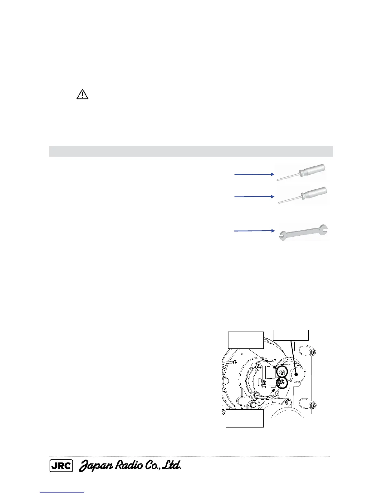
(2) Remove the two screws (M4) that
secure the encoder, and remove the
encoder from the chassis.
Remove the
M4 screw.
Loosen the
M4 screw.
Encoder

 Loading...


