2-13
2.4.2. GPS (J3)
GPS (J3) is used for connection with the GPS.
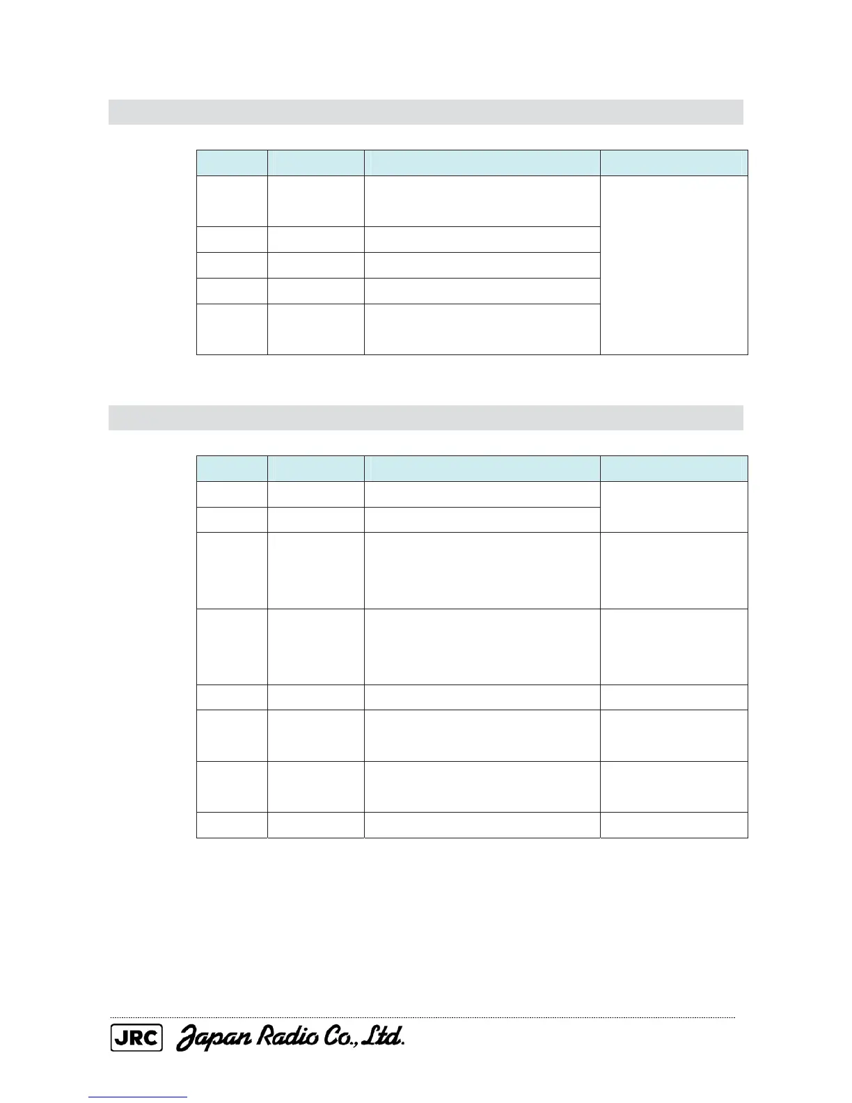
PIN NAME DESCRIPTION APPLICATION
1 +12V
Used for direct connection with a
JRC GPS receiver
2 GND Same as above
3 NAVCOM Data return
4 NAVRX Data input
5 NAVTX
Used for direct connection with a
JRC GPS receiver
GPS
2.4.3. GYRO/COMPASS (J5)
GYRO/COMPASS (J5) is connected when a bearing signal is input to the radar.
PIN NAME DESCRIPTION APPLICATION
1 NSKTX- Signal (+) transmitted to the NSK
2 NSKTX+ Signal (-) transmitted to the NSK
3 NSKRX+
Signal (+) received from the NSK,
GPS compass, or another bearing
sensor (NMEA)
4 NSKRX-
Signal (-) received from the NSK,
GPS compass, or another bearing
sensor (NMEA)
5 GND Power GND for the NSK
6 ALM+ Dry contact output 1
External-buzzer
connection
7 ALM- Dry contact output 2
External-buzzer
connection
8 +5V Power supply (+5 V) for the NSK

 Loading...


