4-5
(3) After transmitting on a long range for about fifteen minutes, return to the service
engineer menu and adjust the tuning.
Perform the adjustment in the service engineer menu until the tuning display bar
on the display unit reaches the eighth calibration mark.
With the service engineer menu open, also make sure the magnetron current is
shown between the fifth and seventh calibration markings.
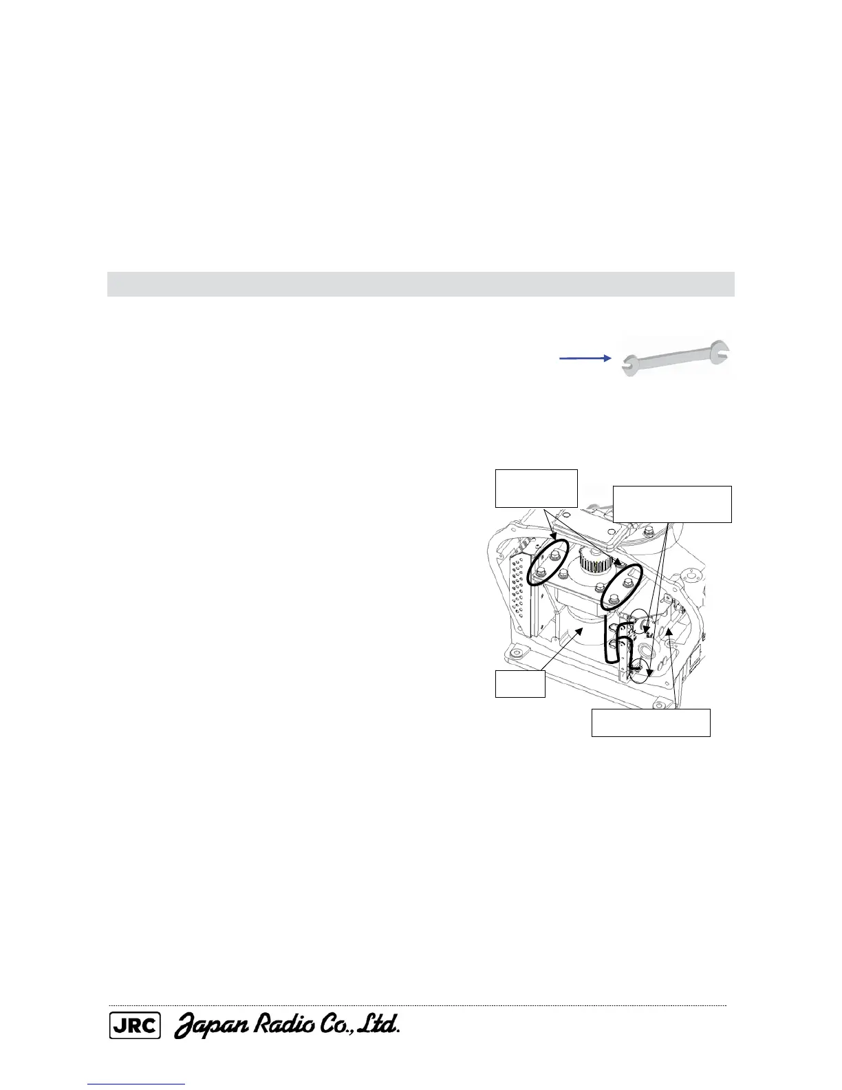
4.1.4. Motor replacement / NKE-2254
[Required tools]
• Single-ended wrench (width across flats 17 mm for M8 bolts)
• Tools for removing the scanner unit covers (See Section 4.1.2)
[Replacement procedure]
(1) Remove the cover from the left (port)
side (see Section 4.1.2), and disconnect
the cables that are connected to the motor
driver circuit from the motor.
(2) Remove the four hexagon bolts (M8),
and remove the motor.
Remove the
four bolts.
Disconnect the two
cables.
Motor
Motor driver circuit

 Loading...


