4-26
[Operation check]
After completing the replacement work, check the operation by following the
procedure below.
(1) Turn on the radar, transmit radar signals when the countdown is finished, and
check that radar images are displayed normally.
4.1.17. Modulation Circuit (CME-363) Replacement for the NKE-2103
[Required tools]
• A Phillips screwdriver for 4 mm screws
• A Phillips screwdriver for 5 mm screws
• Tools for removing the scanner unit covers (See Section 4.1.2)
[Replacement procedure]
(1) Open the top cover (see Section 4.1.2),
and remove the transmitter-receiver unit
(see Section 4.1.6).
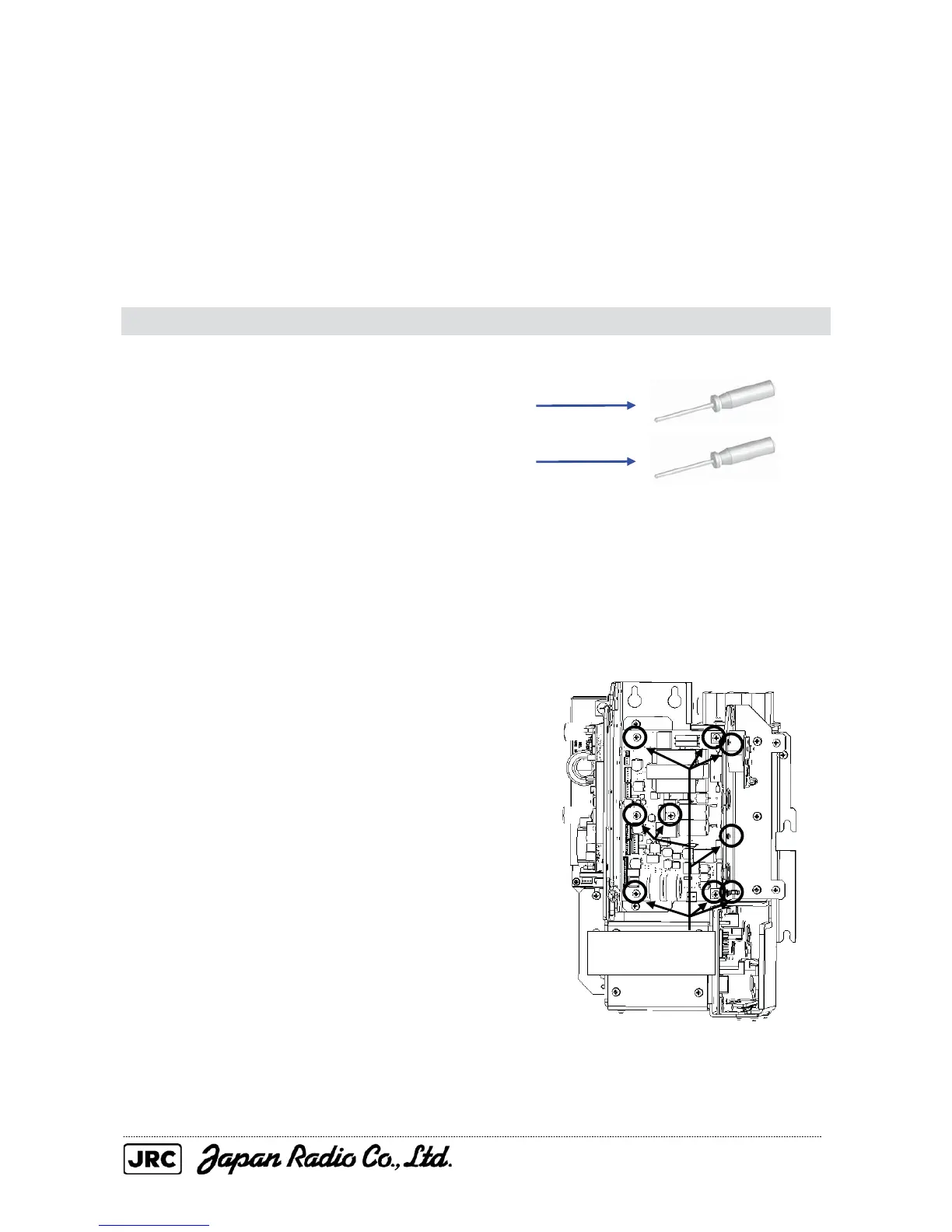
(2) Disconnect the cables from the
modulation circuit, remove the nine screws
(M4) that secure the modulation circuit, and
replace it.
If the heat radiation plate of the
modulator is used, mount the insulating
sheet straight between TR17/TR18 and the
heat radiation plate.
(3) After the modulation circuit replacement,
carry out the work in reverse order of
removal.
Be sure to tighten all the bolts and
screws and connect all the cables.
Remove the nine
screws (M4).

 Loading...


