4-4
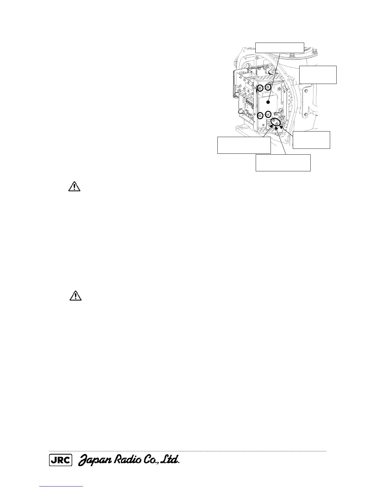
(2) Make sure there is no charge remaining
in the modulation high-voltage circuit board,
and then remove the screws (two M4
screws) holding the magnetron cables
(yellow and green) in place.
(3) Remove the screws (four M4 screws)
holding the magnetron in place, then
replace the magnetron after cutting the
leads (yellow and green) for the
replacement magnetron to an appropriate
length.
Use a shielded secrewdriver because
the contact of the metal tool with
the magnetron causes deterioration
of its performance.
(4) After having replaced the magnetron, reassemble the unit by following the
disassembly procedure in the reverse order.
Do not forget to tighten the bolts and screws, and do not forget to reconnect the
cables.
Extreme care should be taken to connect the leads (yellow and green) to the
magnetron for prevention of contact with other parts or the casing. Contact
may cause them to discharge.
[Operation check]
After having completed the replacement, follow the steps below to check the operation.
(1) Turn on the radar and allow sufficient preheating time (20 - 30 minutes in the
STBY mode).
(2) Start transmission on a short pulse range and change the range to the longer
ranges. Open the service engineer menu and provisionally adjust the tuning.
Whenever operation becomes unstable, immediately return to STBY, wait five to ten
minutes, and then transmit again.
Remove the green
cable.
Remove the yellow
cable.
Magnetron
Remove the
four screws.
Remove the
two screws.

 Loading...


