4-9
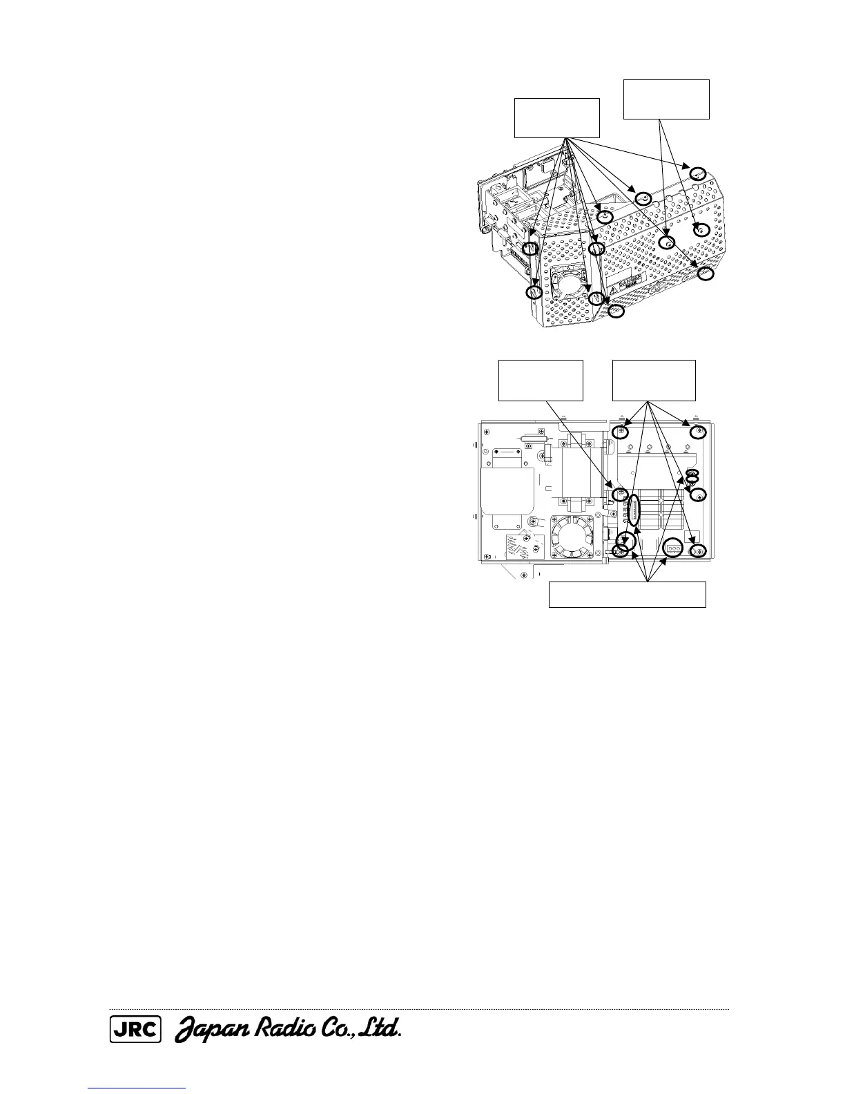
(2) Loosen the screws (nine M4 screws)
holding the cover in place, remove the
screws (two M4 screws) holding the heat
radiation plate in place, and remove the
cover.
(3) Remove the cables connected to the
modulator circuit board, then remove the
screws (five M4 screws) holding the
modulator circuit board in place and the
spacer (one 7 mm (nominal) spacer), and
replace the modulator circuit board.
If reusing the heat radiation plate on the
modulator, be sure to install the thermal
insulation sheet between the TR5-8 and the
heat radiation plate so that it is straight.
(4) After having replaced the modulator circuit
board, reassemble the unit following the
disassembly procedure in the reverse order.
Do not forget to tighten the bolts and
screws, and do not forget to reconnect the
cables.
[Operation check]
After having completed the replacement, follow the procedure below to check the operation.
(1) Turn on the radar and emit radar waves once the countdown is finished, and
check that the radar image is correctly displayed.
Transmit radar signals on a long range and with the service engineer menu open,
also make sure the magnetron current is shown between the fifth and seventh
calibration markings.
Remove the
five screws.
Remove the five cables.
Remove the
spacer.
Loosen the
nine screws.
Remove the
two screws.

 Loading...


