4-12
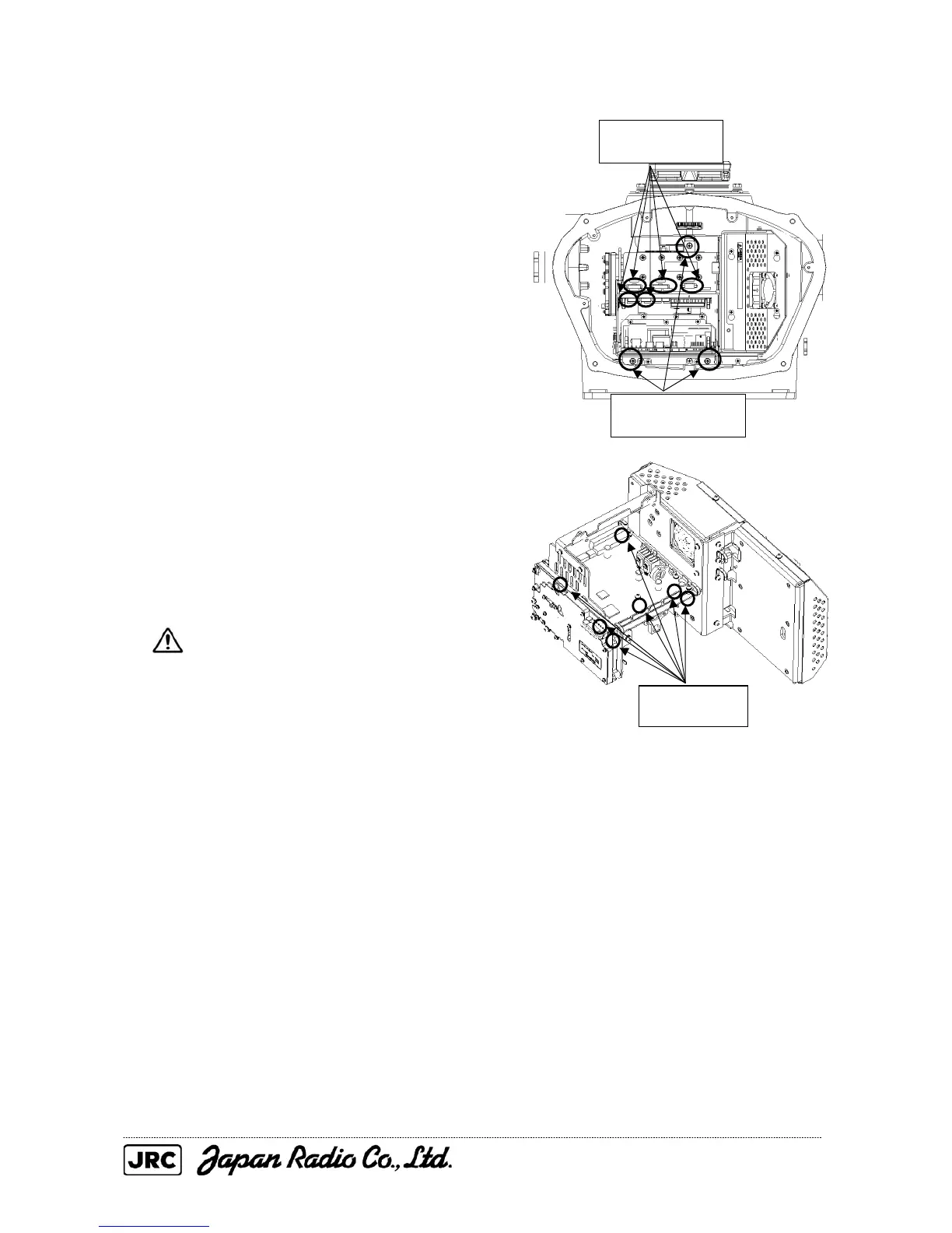
(2) Remove the cover on the right (starboard)
side (see Section 4.1.2), remove the cables
connected to the transmitter-receiver unit
and the screws (three M5 screws) holding
the transmitter-receiver unit in place, and
remove the transmitter-receiver unit.
(3) Remove the cables connected to the T/R
control circuit board and the screws (seven
M4 screws) and replace the T/R control
circuit board.
Set the DIP switch and jumper pins of
the T/R control circuit board to suite
the NKE-2254 (see Section 2.5.5).
(4) After having replaced the T/R control
circuit board, reassemble the unit following
the disassembly procedure in the reverse
order.
Do not forget to tighten the bolts and
screws, and do not forget to reconnect the
cables.
Remove the five
cables.
Remove the three
screws.
Remove the
seven screws.

 Loading...


