4-19
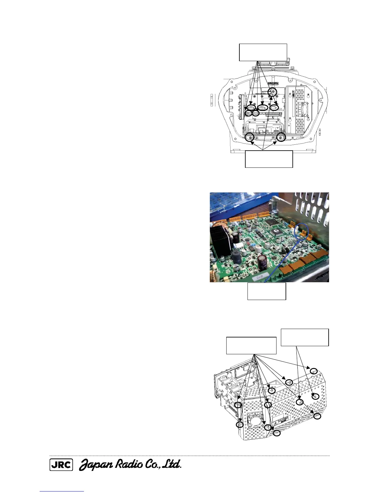
(1) Remove the cover on the right (starboard)
side (see Section 4.1.2), remove the cables
connected to the transmitter-receiver unit
and the screws (three M5 screws) holding
the transmitter-receiver unit in place, and
remove the transmitter-receiver unit.
(2) Remove the cable for the fan that is
connected to the T/R control circuit board.
(3) Loosen the screws (nine M4 screws)
holding the cover in place, remove the
screws (two M4 screws) holding the heat
radiation plate in place, and remove the
cover.
Remove the five
cables.
Remove the
three screws.
Remove the
cable.
Loosen the nine
screws.
Remove the two
screws.

 Loading...


