4-23
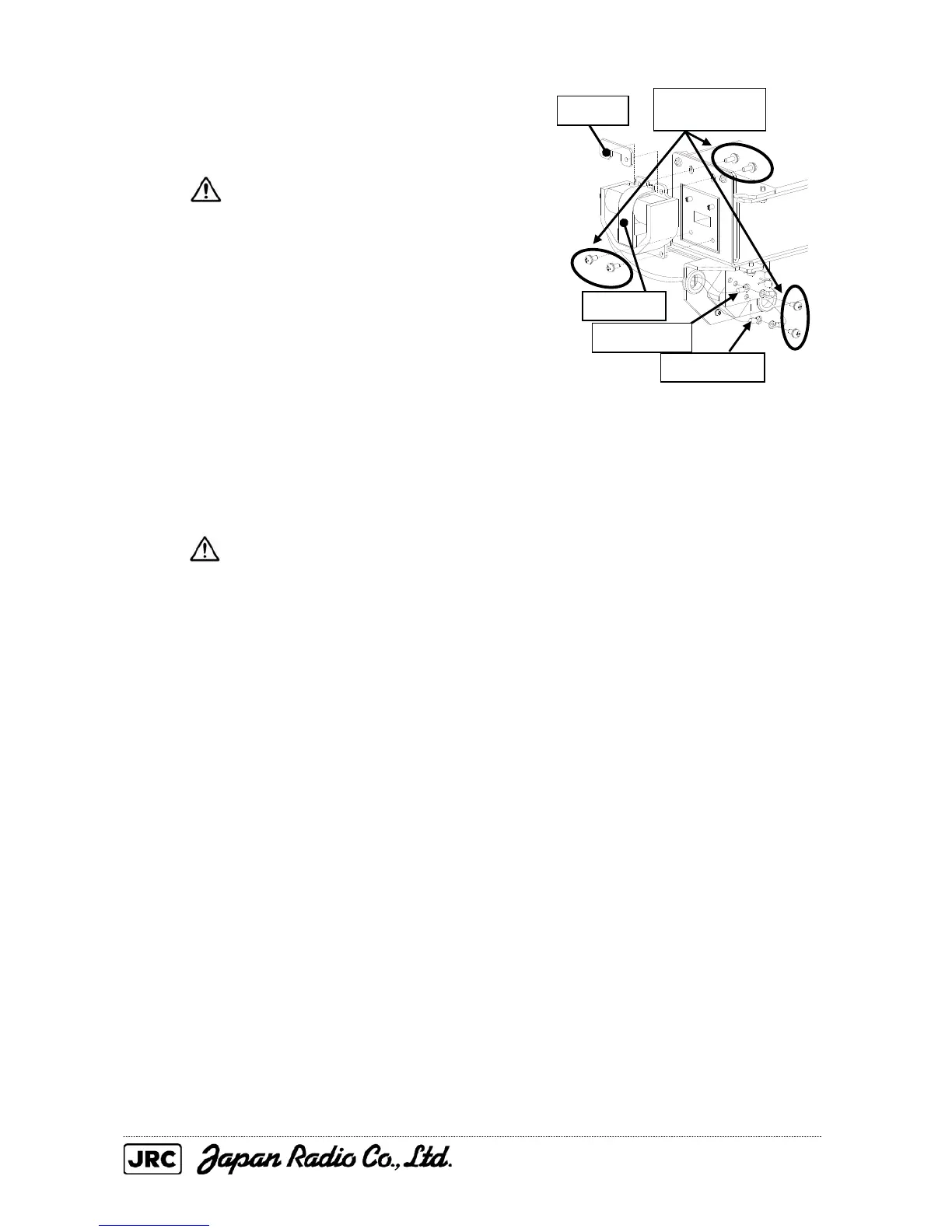
(3) Remove the six screws (M4) that secure
the magnetron, and replace the magnetron.
A shielded screwdriver shall be
used for magnetron replacement.
Touching the magnetron with metal
(a tool) causes performance
deterioration.
(4) Adjust the lead wires (yellow and green) of the new magnetron to an appropriate
length, and tighten the screws to secure the cables.
After the magnetron replacement, carry out the work in reverse order of removal.
Be sure to tighten all the bolts and screws and connect all the cables.
Be careful that the lead wires (yellow and
green) of the magnetron do not touch
other parts or the chassis.
Bringing the lead wires into contact with
them can cause the discharge.
[Operation check]
After completing the replacement work, check the operation by following the
procedure below.
(1) Turn on the radar, and allow sufficient preheating time (about 20 to 30 minutes in
the STBY state).
(2) Start transmission in a short pulse range, and gradually change to longer ranges.
At this time, open the service engineer menu and perform provisional tuning
adjustment.
If operation becomes unstable in the meantime, immediately change the
equipment back into the STBY state, leave it there for 5 to 10 minutes, and restart
transmission.
Nut plate
Remove the six
screws.
Magnetron
Cable: Green
Cable: Yellow

 Loading...


