4-37
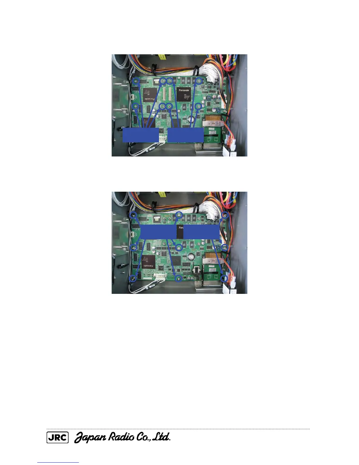
(4) Remove the eight hexagonal support posts that secure the radar processing circuit.
(Socket wrench for 5.5 mm bolts)
(5) Remove the nine screws that secure the radar processing circuit, and replace it.
(Phillips screwdriver for 3 mm screws)
[Mounting]
(1) Confirm that the DIP switch settings are the same between the old and new radar processing
circuits.
(2) Assemble the unit in reverse order of removal.
[Operation check]
(1) Check that the equipment starts normally.
(2) Check that an error message is not displayed.
(3) Restore the setup data you saved, and set the transmission time and operating time of the
scanner unit you wrote down.
(4) Transmit radar signals and check that radar images are displayed normally.
Remove Remove
Remove Remove

 Loading...


