EasyManuals Logo

JRC JMA-5212-4/6 Service Manual

JRC JMA-5212-4/6
172 pages
To Next Page IconTo Next Page
To Previous Page IconTo Previous Page
Page #98 background imageLoading...
Page #98 background image
4-42
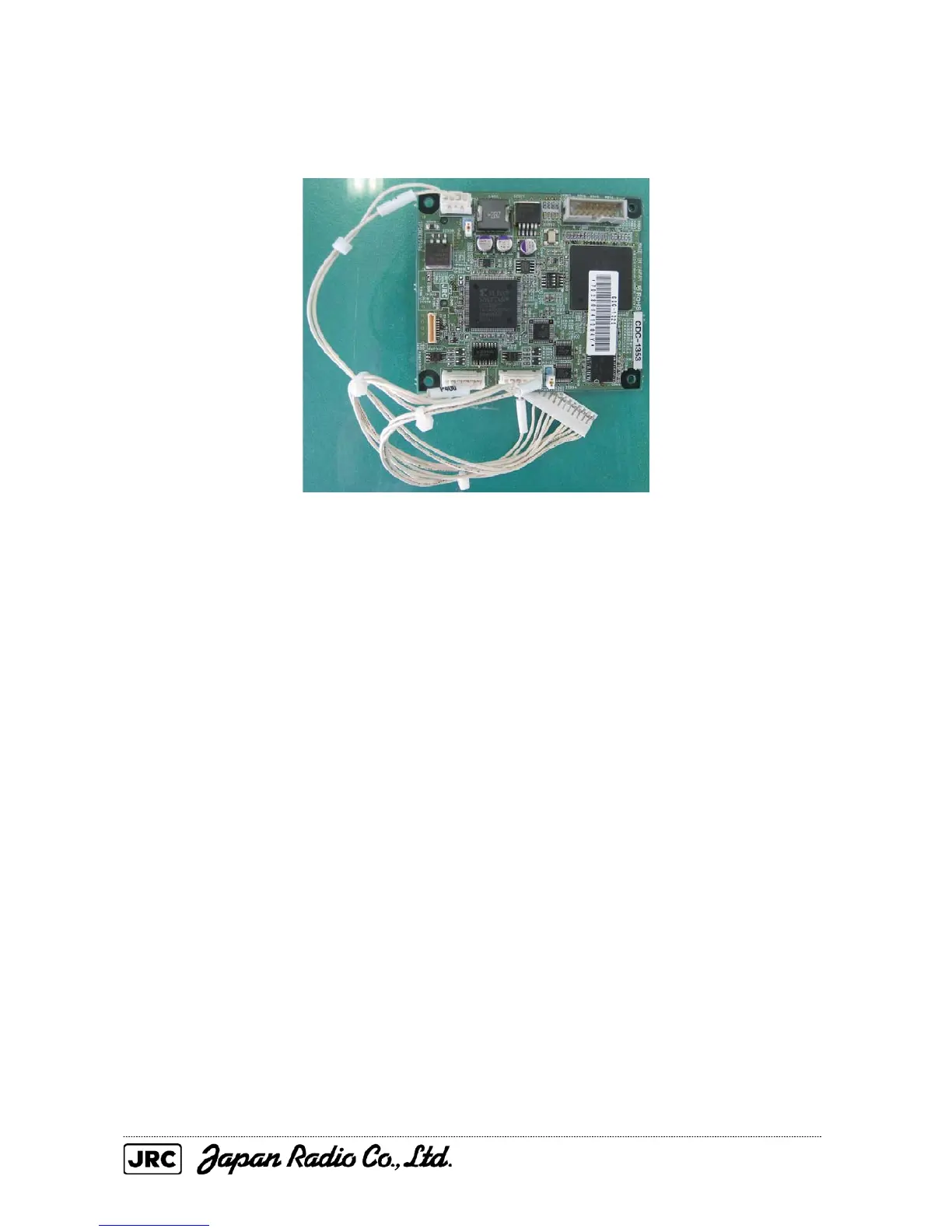
(4) Remove the four screws that secure the AIS processing circuit, and replace it.
(Phillips screwdriver for 3 mm screws)
[Mounting]
(1) Confirm that the DIP switch and short plug settings are the same between the old and new AIS
processing circuits.
(2) Connect the connector-attached cables to the new AIS processing circuit.
(3) Assemble the unit in reverse order of removal.
[Operation check]
(1) Check that the equipment starts normally.
(2) Check that an error message is not displayed.

Table of Contents

Other manuals for JRC JMA-5212-4/6

Questions and Answers:

Question and Answer IconNeed help?

Do you have a question about the JRC JMA-5212-4/6 and is the answer not in the manual?

JRC JMA-5212-4/6 Specifications

General IconGeneral
BrandJRC
ModelJMA-5212-4/6
CategoryMarine Radar
LanguageEnglish

Related product manuals