– 85 –
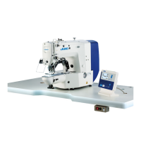
(2) Input signal check
It is possible to check the input conditions of the pedal switches and various sensors etc.
1) Selecting the sensor item
Press ITEM SELECT key
❻
to select the
sensor to perform the conrmation. (Sensor items
that are displayed on the left side of screen is
changed over.)
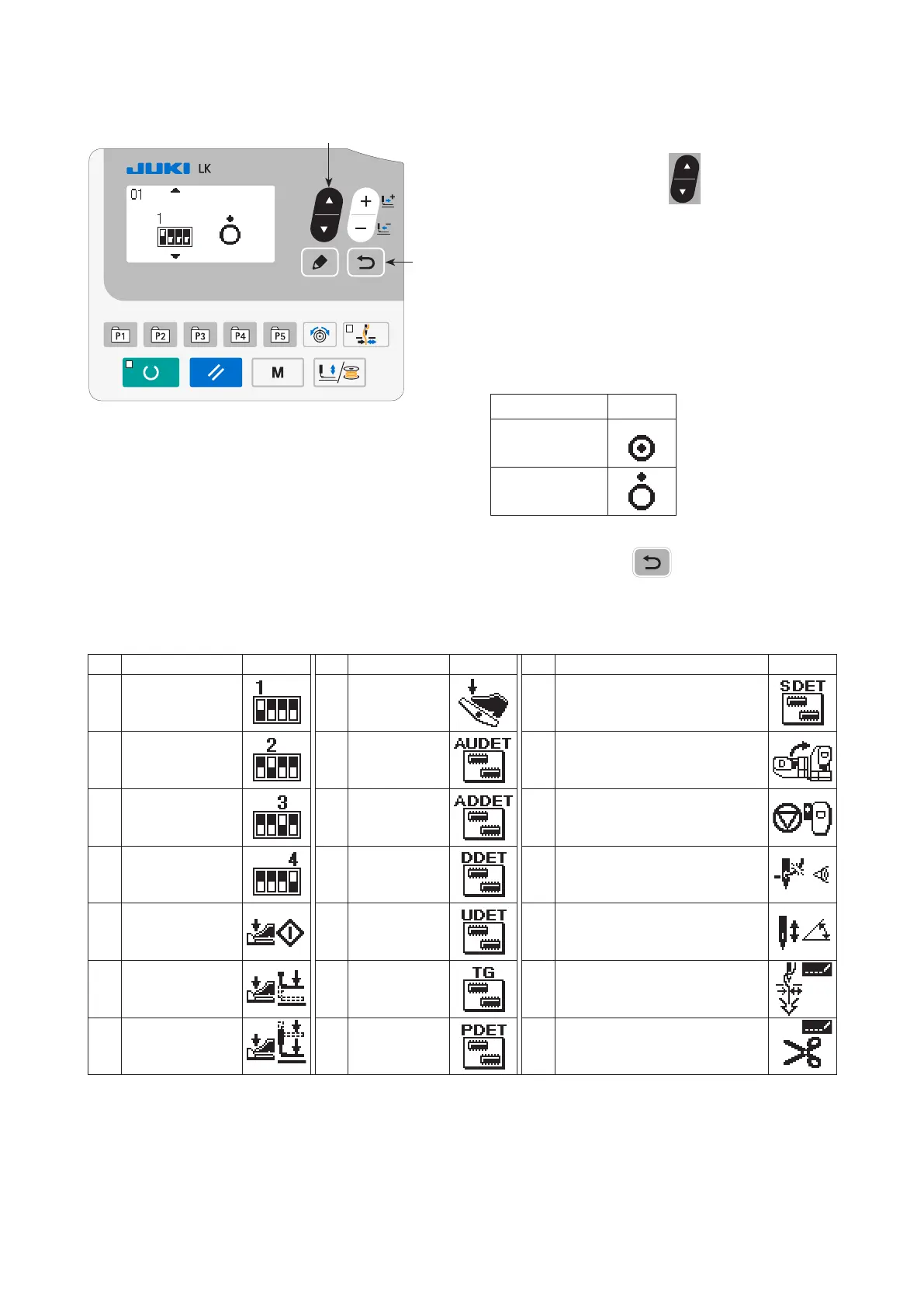
Sensor that can be conrmed are as follows.
In addition, the display screen of right half will
change as follows by ON / OFF of the sensor.
State of sensor Display
Sensor ON
Sensor OFF
2) When RETURN key
❾
is pressed, the
screen returns to the check program screen.
❻
❾
No. Sensor name Display No. Sensor name Display No. Sensor name Display
01 DIP switch 1 08
Analog pedal
sensor
15 SDET sensor
02 DIP switch 2 09
AUDET sen-
sor
16 Head tilt switch
03 DIP switch 3 10
ADDET sen-
sor
17 Temporary stop switch
04 DIP switch 4 11 DDET sensor 18
Thread breakage detection
switch
05
Start switch
(pedal)
12 UDET sensor 19
Sewing machine needle bar
angle (0 to 359)
06
Work clamp foot
1 switch (pedal)
13 TG sensor 20 Suction nozzle
07
Work clamp foot
2 switch (pedal)
14 PDET sensor 21
Shorter thread remaining
thread trimmer cylinder switch
(Remarks) The description only uses the panel
diagram of the standard specication.

 Loading...