• ACX1000 and ACX1100 Routers Hardware and CLI Terminology Mapping on page 5
• LEDs on ACX1000 and ACX1100 Routers on page 35
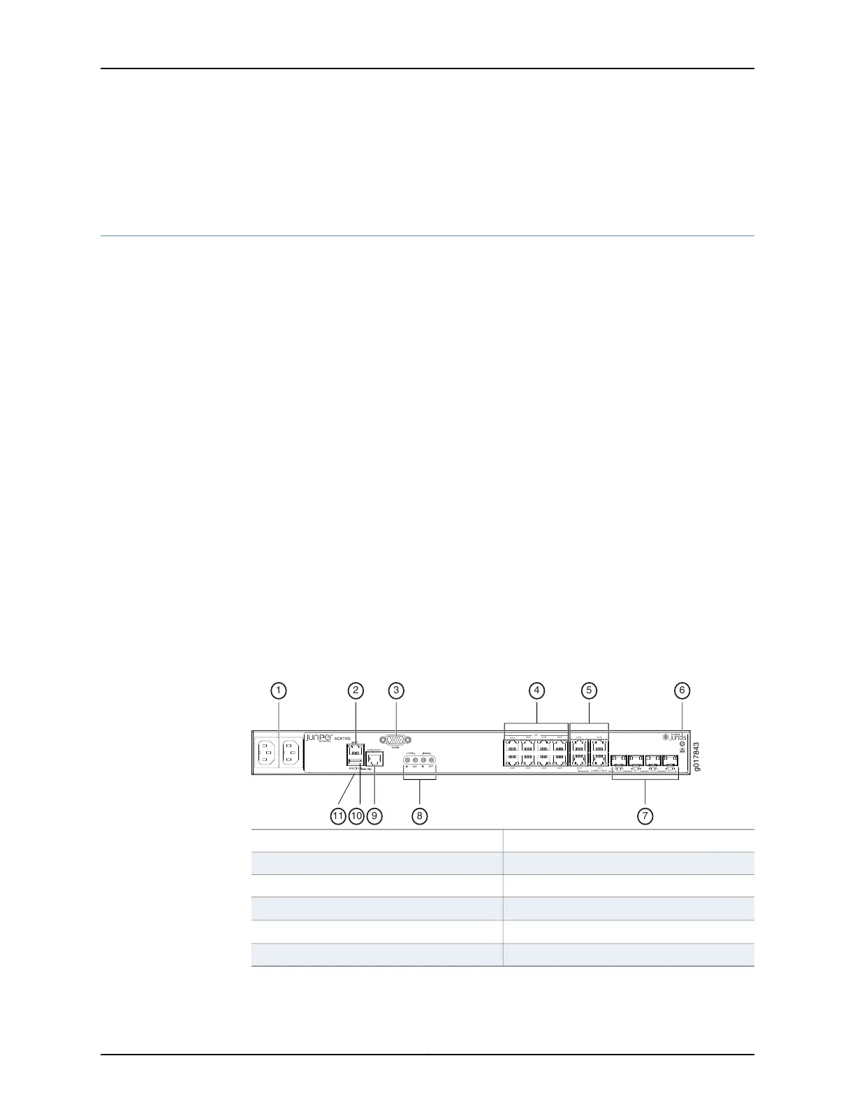
Front Panel of an ACX1100 Router
The front panel of an ACX1100 router consists of the following components (see
Figure 12 on page 31 and Figure 13 on page 32):
•
Chassis status LED labeled SYS
•
AC power inlets or DC power terminals
•
USB port for upgrading Junos OS
•
Management Ethernet port labeled MGMT
•
Console or auxiliary port labeled CONSOLE/AUX
•
Alarm contact port labeled ALARM—accepts a DE-15 alarm cable
•
External clocking input port labeled EXT REF CLK IN
•
External clocking ports supporting 1PPS and 10MHz input and output
•
Network ports and corresponding status LEDs:
•
Eight Gigabit Ethernet (GE) RJ-45 ports labeled 0/0/0 through 0/0/7
•
Combination ports labeled 0/1/0 through 0/1/3, either:
•
Four Gigabit Ethernet RJ-45 ports
•
Four Gigabit Ethernet SFP ports that accept SFP transceivers
Figure 12: Front Panel of the AC-Powered ACX1100 Router
g017843
0/0/0
0/0/1 0/0/2 0/0/3
0/0/4
0/0/5 0/0/6 0/0/7
GE
0/1/0
0/1/1
0/1/2 0/1/3
0/1/0
0/1/1 0/1/2 0/1/3
CONSOLE/AUX
COMBO PORTS
8 7
5 643
91011
1 2
7—1— Combination Gigabit Ethernet SFP portsAC inlets
8—2— External clocking portsManagement Ethernet port
9—3— Console or auxiliary portAlarm contact port
10—4— USB port
Gigabit Ethernet (GE) ports
11—5—
System (SYS) LED
Combination Gigabit Ethernet RJ-45 ports
6—ESD point
31Copyright © 2017, Juniper Networks, Inc.
Chapter 2: Chassis Components and Descriptions

 Loading...


