Console/Auxiliary Port Connector Pinout on ACX Series Routers
The port on the front panel labeled CONSOLE/AUX is an asynchronous serial interface
that accept an RJ-45 connector. Use a cable with the pinouts described in
Table 27 on page 73 to connect the Routing Engine to an auxiliary or console management
device.
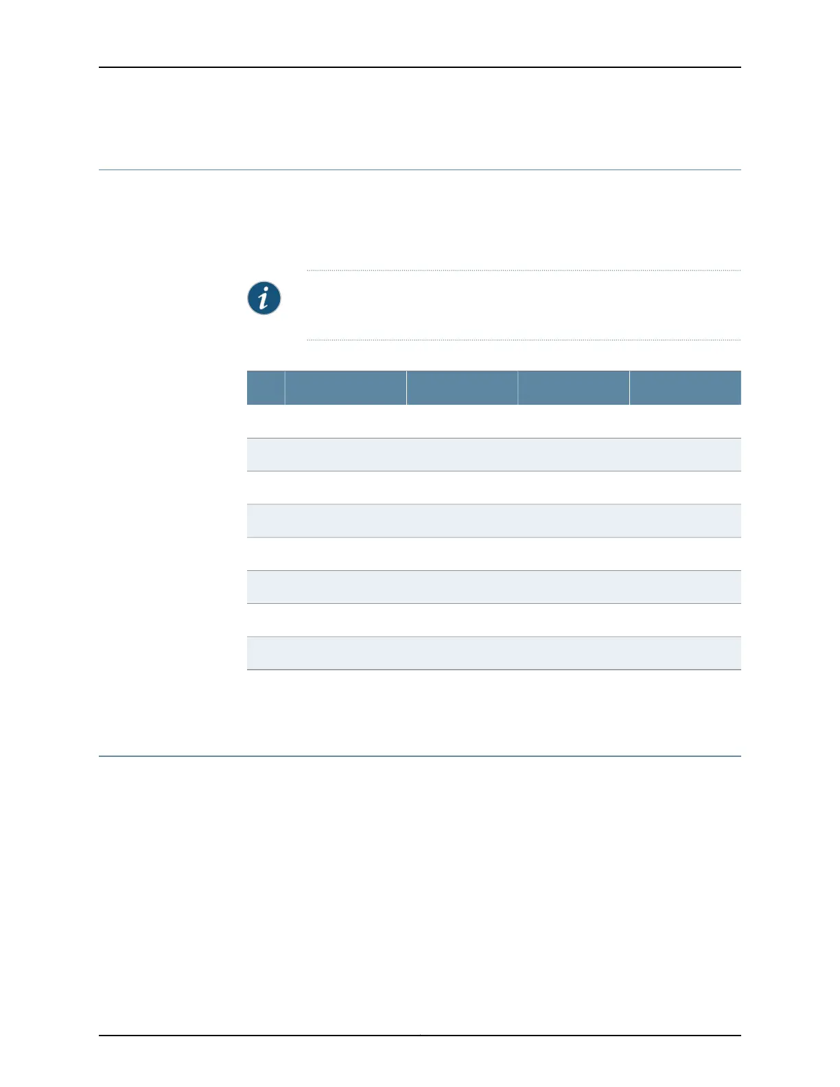
NOTE: You must use a shielded twisted pair (STP) cable for both outdoor
and indoor deployments.
Table 27: Connector Pinout for the Console/Auxiliary Port
DirectionCPUDescriptionSignalPin
OutRouting EngineRequest to SendRTS1
Out1588 CPUTransmit DataTXD2
OutRouting EngineTransmit DataTXD3
––Signal GroundGround4
––Signal GroundGround5
InRouting EngineReceive DataRXD6
In1588 CPUReceive DataRXD7
InRouting EngineClear to SendCTS8
Related
Documentation
Management Port Connector Pinout Information for ACX Series Routers on page 73•
Management Port Connector Pinout Information for ACX Series Routers
The management port on an ACX Series router labeled MGMT uses an RJ-45 connector
to connect to a management device for out-of-band management.
The port uses an autosensing RJ-45 connector to support a 10/100Base-T connection.
Two LEDs indicate link/activity on the port and the administrative status of the port.
Table 28 on page 74 provides the pinout information for the RJ-45 connector for the
management port.
73Copyright © 2017, Juniper Networks, Inc.
Chapter 12: Alarm, Management, and Clocking Cable Specifications and Pinouts

 Loading...


