•
External clocking ports supporting 1PPS and 10MHz input and output
•
Network ports and corresponding status LEDs:
•
Sixteen T1/E1 ports labeled 0/0/0 through 0/0/15
•
Four Gigabit Ethernet (GE) ports labeled 1/0/0 through 1/0/3
•
Combination (COMBO) ports labeled 1/1/0 through 1/1/3, either:
•
Four Gigabit Ethernet RJ-45 ports
•
Four Gigabit Ethernet SFP ports
•
Two Gigabit Ethernet (GE) ports labeled 1/2/0 through 1/2/1 that accept SFP transceivers
•
Two 10-Gigabit Ethernet (XE) ports labeled 1/3/0 and 1/3/1 that accept SFP+ transceivers
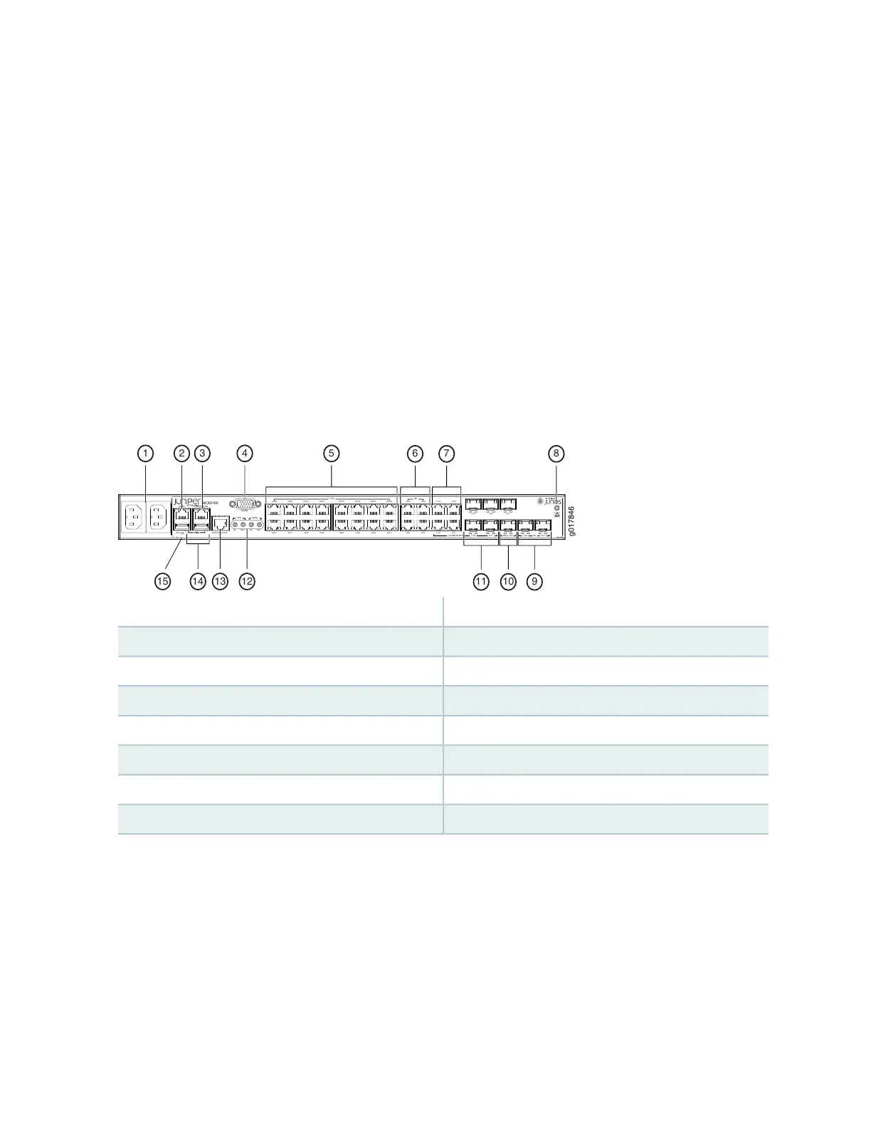
Figure 10: Front Panel of the AC-Powered ACX2100 Router
g017846
ACX2100
MGMT CONSOLE/AUX
SYS
0 1
EXT REF CLK IN
ALARM
OUTIN IN OUT
0/0/8
0/0/0
0/0/9
0/0/1
0/0/10
0/0/2
0/0/11
0/0/3
0/0/12
0/0/4
0/0/13
0/0/5
0/0/6
0/0/14
0/0/7
0/0/15
1/0/0
1/0/2
1/0/1
1/1/11/1/0
1/0/3 1/1/2
GE
1/1/3
COMBO PORTS XE
1/3/0
1/3/1
T1/E1
1PPS 10MHz
GE
1/1/0 1/1/1
1/2/0
1/1/2 1/1/3 1/2/1
54
1215
1 2
14 13
3
10
8
9
7
11
6
9—1— Ten-Gigabit Ethernet SFP+ portsAC inlets
10—2— Gigabit Ethernet SFP portsManagement Ethernet port
11—3— Combination Gigabit Ethernet SFP portsConsole or auxiliary port
12—4— External clocking portsAlarm contact port
13—5— External clocking input portT1/E1 network ports
14—6— USB portsGigabit Ethernet network ports
15—7— System LEDCombination Gigabit Ethernet RJ-45 ports
8—ESD point
49