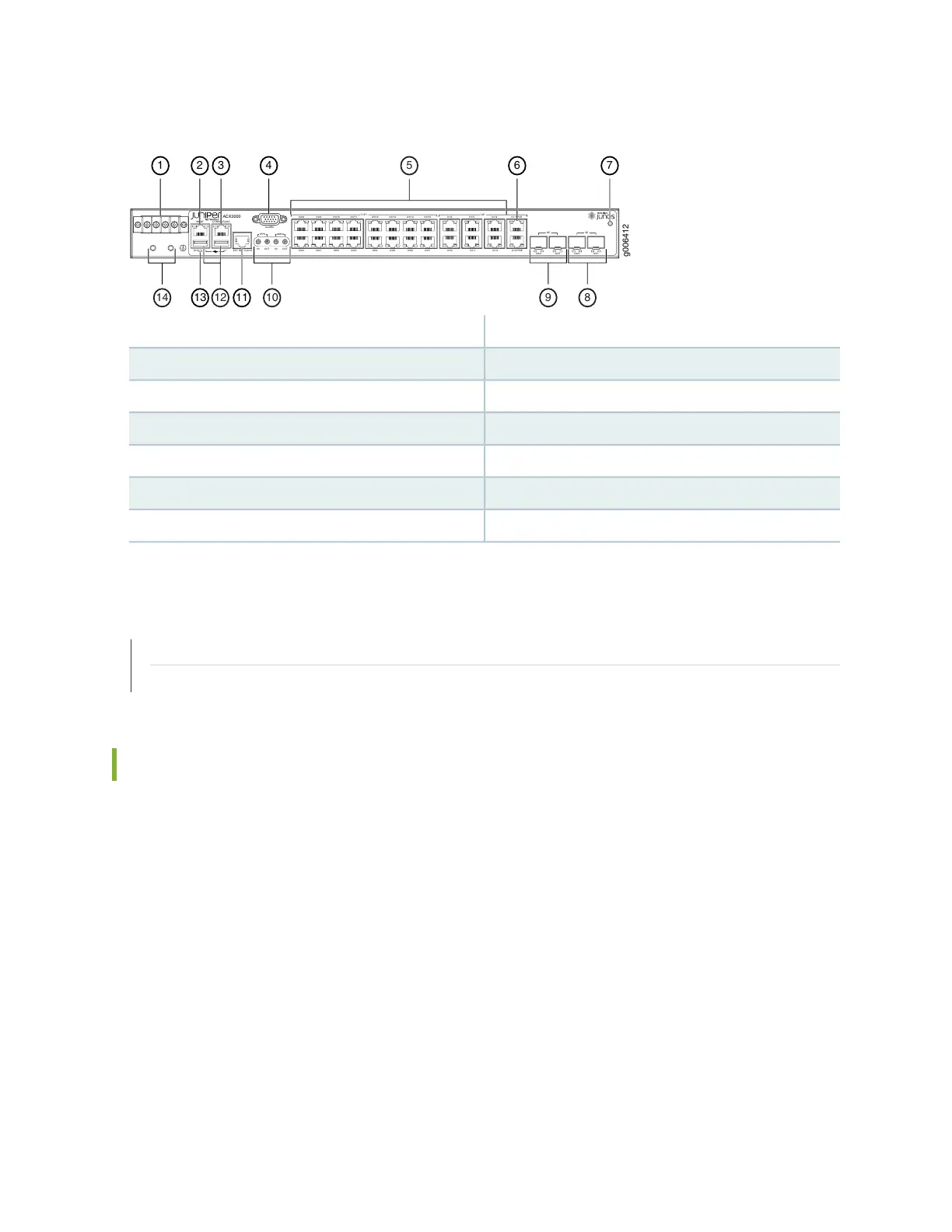
Figure 9: Front Panel of the ACX2000 Router
ACX2000
MGMT
SYS 0 1
CONSOLE/AUX
ALARM
1PPS
10MHz
IN OUT
IN
OUT
T1/E1
0/0/4
0/0/12
0/0/5
0/0/13
0/0/6
0/0/14
0/0/7
0/0/15
0/0/0
0/0/8
0/0/1
0/0/9
0/0/2
0/0/10
0/0/3
0/0/11
0/1/0
0/1/4
0/1/1
0/1/5
0/1/2
0/1/6
0/1/3 POE
0/1/7 POE
GE
0/2/0
0/2/1 0/3/0 0/3/1
g006412
EXT REF CLK IN
GE
XE
1 2 3 4
13
5
9
1014
76
8
1112
8—1— 10-Gigabit Ethernet SFP+ portsDC terminals
9—2— Gigabit Ethernet SFP portsManagement Ethernet port
10—3— External clocking portsConsole or auxiliary port
11—4— External clocking input portAlarm contact port
12—5— USB portsT1/E1 and RJ-45 Gigabit Ethernet network ports
13—6— System LEDPoE Gigabit Ethernet ports
14—7— Grounding terminalsESD point
SEE ALSO
ACX2000 and ACX2100 Universal Metro Router Overview | 17
LEDs on ACX2000 and ACX2100 Routers | 57
Front Panel of an ACX2100 Router
The front panel of an ACX2100 router consists of the following components (see Figure 10 on page 49
and Figure 11 on page 50):
•
Chassis status LED labeled SYS
•
AC power inlets or DC terminals
•
Two USB ports for upgrading Junos OS
•
Management Ethernet port labeled MGMT
•
Console or auxiliary port labeled CONSOLE/AUX
•
Alarm contact port labeled ALARM—accepts a DE-15 alarm cable
•
External clocking input port labeled EXT REF CLK IN
48