c. Tighten the screws on the PSM terminals until snug using the screwdriver. Do not overtighten—apply
between 5 in-lb (0.56 Nm) and 6 in-lb (0.68 Nm) of torque to the screws.
CAUTION: The V+ terminals are shunted internally, as are the V– terminals.
The same polarity terminal can be wired together from the same source to
provide an additional current path in a higher power chassis. Do not connect
the terminals to different sources.
8. Replace the terminal block cover.
9. Close the input 2-pole circuit breaker.
NOTE: The switch powers on as soon as power is provided to the PSM. There is no power
switch on the device.
10. Verify that the IN and OUT LEDs on the PSM are lit green and are on steadily.
CAUTION: A system reboot with Routing Engine FPGA version 7.1 might not
successfully boot the Junos OS software. In case of a system reboot failure, you
need to power cycle the switch. To check the current FPGA version, issue the
show chassis firmware command.
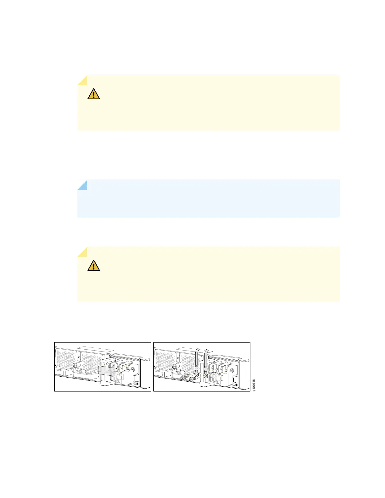
Figure 67: Connect DC Power Cable to an ACX5400 Router
105