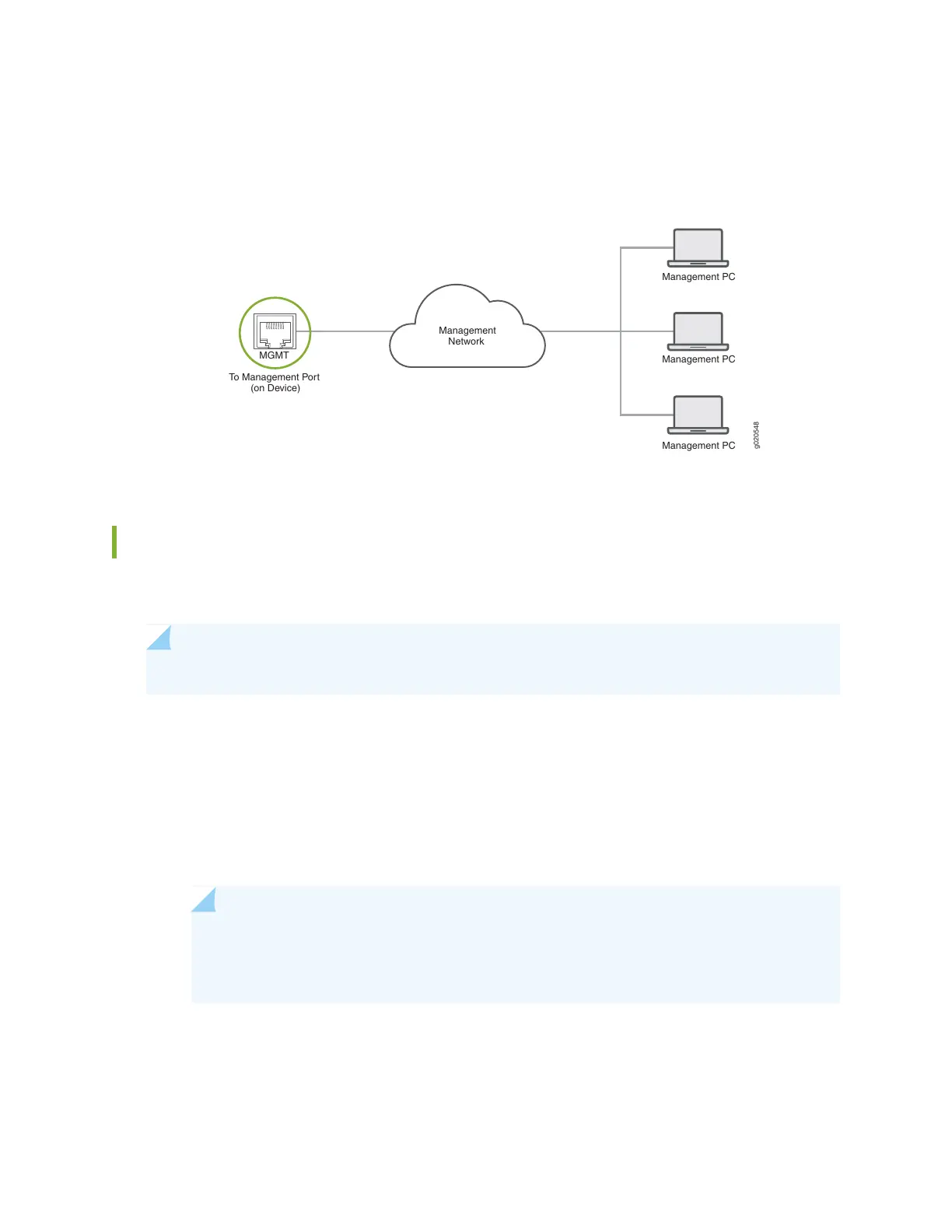
2. Connect the other end of the cable to the management PC (see Figure 70 on page 108).
Figure 70: Connect an ACX5400 Router to a Network for Out-of-Band Management
g020548
Management PC
Management PC
Management PC
Management
Network
To Management Port
(on Device)
MGMT
Connect an ACX5400 Router to External Clocking and Timing Devices
The ACX5400 router has two SMB connector ports that support 1-PPS and 10-MHz timing devices.
NOTE: Ensure that you use a cable of 3 m or less in length for the 10-MHz and 1-PPS connectors.
To connect the SMB to BNC coaxial cable to the external clocking input port:
1. Connect one end of the SMB to BNC coaxial cable to either the 1-PPS connector or the 10-MHz
connector on the router.
2. Connect the other end of the SMB to BNC coaxial cable to the 1-PPS or 10-MHz measurement
equipment.
NOTE: Ensure that the 10-MHz or 1-PPS source network equipment contains low-voltage
complementary metal oxide semiconductor (CMOS) or is compatible with low-voltage
(3.3 V) transistor-transistor logic (TTL).
108