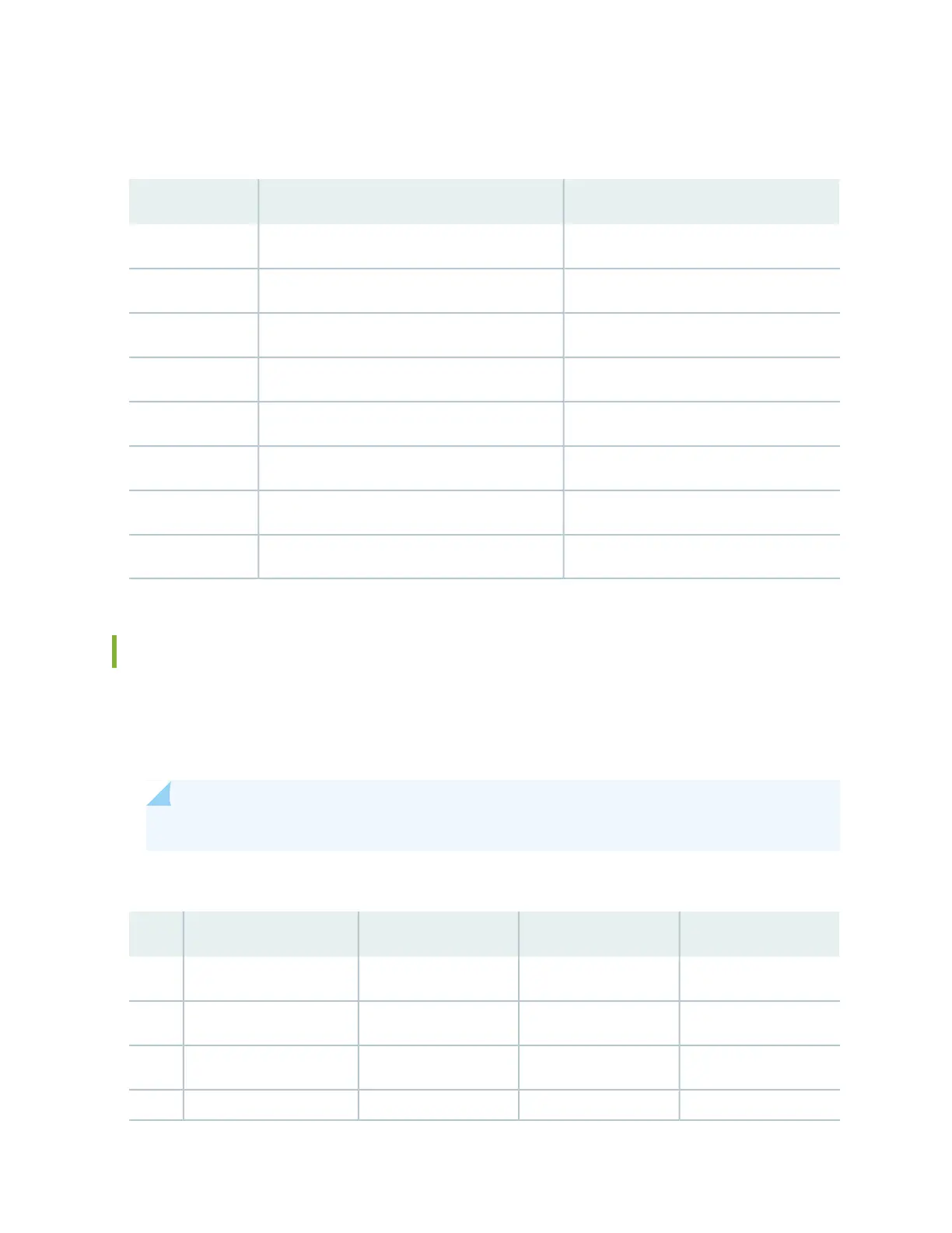
Table 37 on page 81 provides the pinout information for the RJ-45 connector for the management port.
Table 37: Management Port Connector Pinout Information
DirectionDescriptionPin
In/OutTRD[0]-1
In/OutTRD[0]+2
In/OutTRD[1]-3
In/OutTRD[1]+4
In/OutTRD[2]-5
In/OutTRD[2]+6
In/OutTRD[3]-7
In/OutTRD[3]+8
Console or Auxiliary Port Connector Pinout on ACX Series Routers
The port labeled CONSOLE/AUX on the front panel is an asynchronous serial interface that accept an
RJ-45 connector. Use a cable with the pinouts described in Table 38 on page 81 to connect the Routing
Engine to an auxiliary or console management device.
NOTE: You must use a shielded twisted pair (STP) cable for both outdoor and indoor deployments.
Table 38: Connector Pinout for the Console/Auxiliary Port
DirectionCPUDescriptionSignalPin
OutRouting EngineRequest to SendRTS1
Out1588 CPUTransmit DataTXD2
OutRouting EngineTransmit DataTXD3
––Signal GroundGround4
81