NOTE: There are four bicolor lane LEDs for each QSFP28 port that are located just below the
QSFP28 ports. The first LED is used and the remaining LEDs are not used when the port is
configured as a 40-Gigabit Ethernet or 100-Gigabit Ethernet interface, and connected to a
QSFP28 transceiver. All four LEDs are used when the port is configured as a 10-Gigabit Ethernet
or 25-Gigabit Ethernet interface, and the port is connected using an optical split cable (breakout
cable) or a direct attach copper breakout (DACBO) cable.
Table 12 on page 43 describes how to interpret CFP2 port LEDs.
Table 12: CFP2 Port LEDs on ACX5448-D Routers
DescriptionStateColorMode
Indicates that the port speed is 200 Gbps, and
there is some activity.
On or flashingGreen100-Gigabit
Ethernet or
200-Gigabit
Ethernet
Indicates that the port speed is 100 Gbps, and
there is some activity.
On or flashingAmber
There is no link on the port.UnlitOff
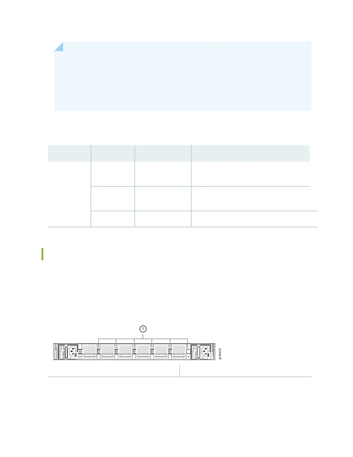
Fan Status LEDs on ACX5400 Routers
The fan modules on ACX5400 routers do not have any LEDs—the fan status LEDs are located next to the
fan module slots on the ACX5400 chassis. Figure 28 on page 43 shows the location of the LED next to
the fan module.
Figure 28: Fan Status LEDs on ACX5400 Routers
1—Fan LEDs
Table 13 on page 44 describes the function of the fan status LED.
43