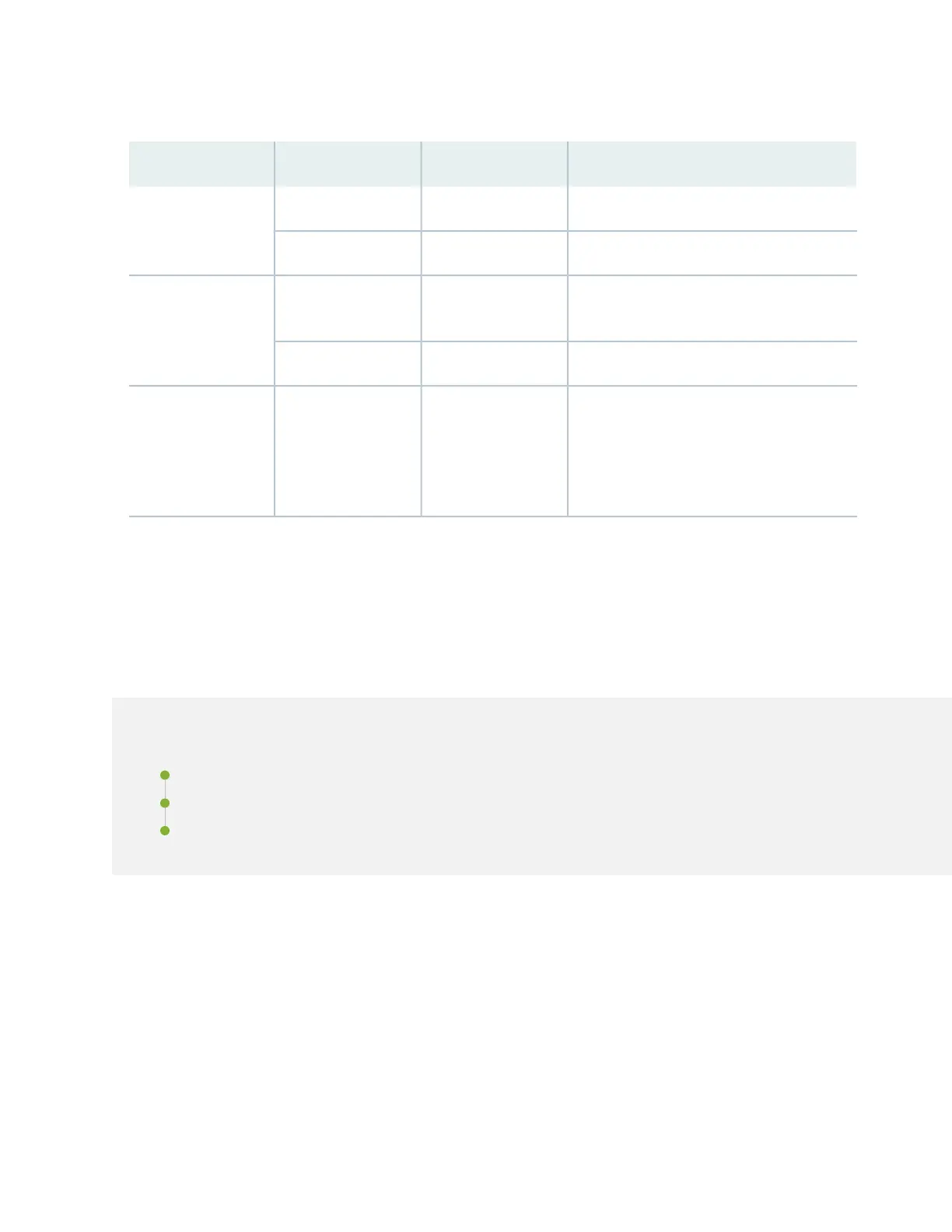
Table 15: DC Power Supply LEDs on ACX5400 Routers
DescriptionStateColorName
There is no input power to the PSM.OffUnlitIN
There is input DC power to the PSM.On steadilyGreen
There is no output voltage from the PSM.
Check the PSM.
OffUnlitOUT
There is output voltage from the PSM.On steadilyGreen
An error is detected in the PSM. Replace the
PSM as soon as possible. To maintain proper
airflow through the chassis, leave the PSM
installed in the chassis until you are ready to
replace it.
On steadilyAmber! (fault)
Cooling System and Airflow in ACX5448, ACX5448-D,
and ACX5448-M Routers
IN THIS SECTION
Fan Modules | 48
Fan Module and Power Supply Requirement | 50
Fan Module Status | 51
The cooling system in ACX5400 routers consists of six fan modules and a single fan in each power supply
module (PSM). The ACX5400 routers can be set up to work in the following airflow directions:
•
Airflow in (AFI)—Air comes into the router through the vents in the field-replaceable units (FRUs)
•
Airflow out (AFO)—Air comes into the router through the vents in the front panel.
47