23
Construction and Function
Overview
2
3
3
1
4
7
5
6
8
bn
bn
bo
bo
bp
bl
bq
9
br
bm
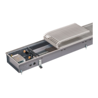
The unit can be supplied as a left-handed or
right-handed unit (position of connections).
The diagrams used in this manual relate to
left-handed units. The right-handed model is a
mirror-image.
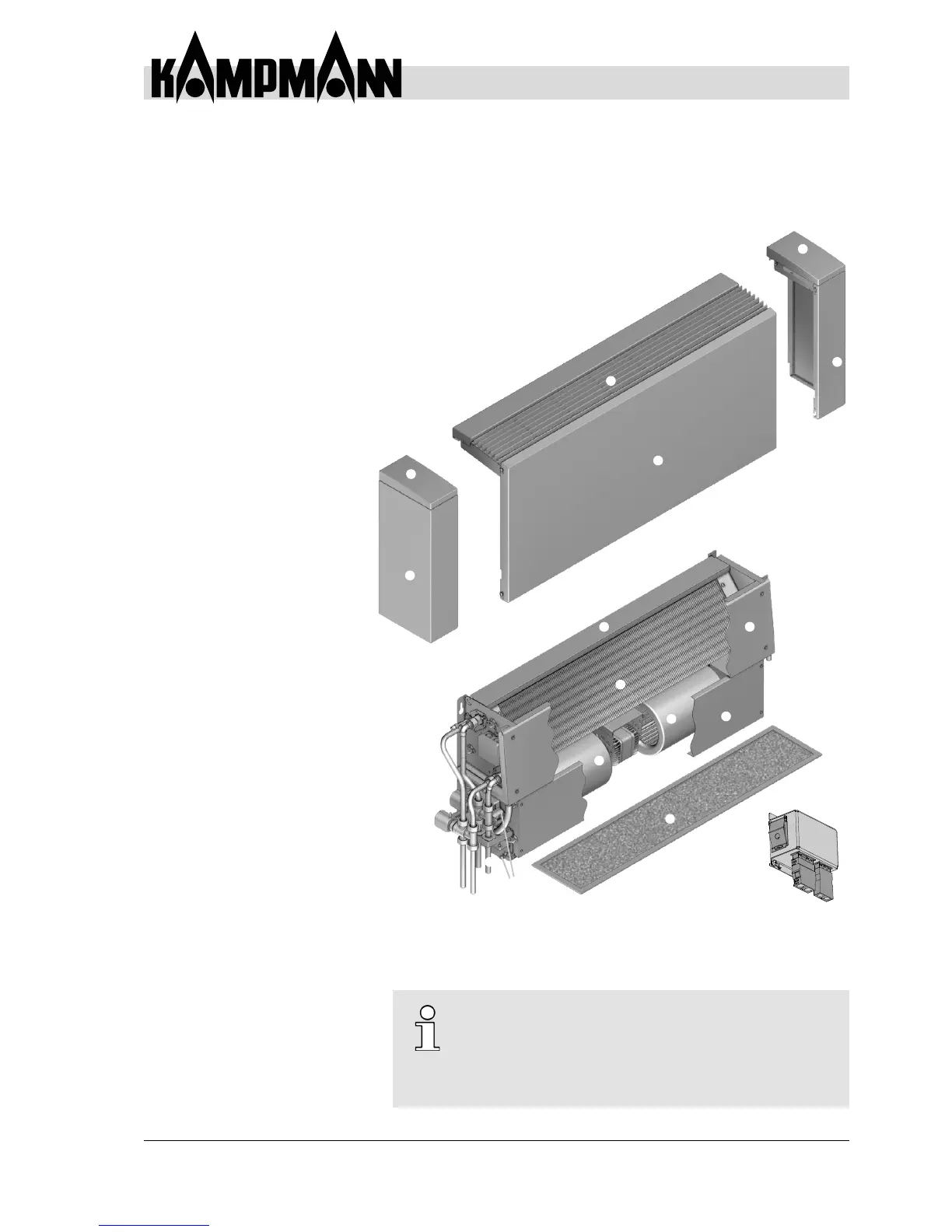
4 Construction and Function
4.1 Overview
1
Cu/Al heat exchanger
2
Rear panel and main brackets
3
Fan unit
4
Air vent
5
/
6
Valve kit (including electrical
actuators and valves )
(accessories)
7
Main condensate tray with a drain
connection on both sides
8
Electrical junction box
(plastic junction box with
electro-mechanical model 00)
9
Filter element
bl
Casing air outlet grille, RAL 9006
(accessory)
bm
Casing front panel with wall
connection panel, RAL 9016
(accessory)
bn
Casing side mullions, RAL 9016
(accessory)
bo
Casing access opening, RAL 9016
(accessory)
bp
Condensatepumpwithoat
switch (accessory)
bq
Side condensate tray
(accessories)
br
Front panel - fan unit
Fig. 9: Exploded view
Recirculation air Venkon fan coil wall-mounted unit with
wall casing
b