50
50
Installation and Connection
Pipe connections
Theowandreturnconnectionsarelocatedasstandardontheleftsideof
the unit, seen from the front panel.
Route the pipes so that no mechanical stresses are transferred to the heat
exchanger and that the unit can be accessed with ease for maintenance
and repair work. Proceed as follows when hydraulically connecting up the
Venkonfancoil:
•
Shut off the heating/cooling medium and prevent it from being opened
accidentally before connecting to on-site pipework and making the
hydraulic connections on the basic unit, as there is a danger of scalding
from escaping heating medium!
•
With cooling units there is a danger to the user from the cold and a
danger to the environment from the use of glycol. Take appropriate
safety measures.
•
Removeprotectivecapsfromtheowandreturn.
•
With cooling mode, route pipes and valves directly over the side
condensate tray (accessory) to drain any condensate produced on the
pipes during cooling mode into the tray.
•
Seal and screw in connections, holding the nut to prevent it from shearing
off and twisting.
•
When connecting the unit to the on-site pipework, make sure that you
use a suitable tool to hold the unit‘s water connections in place!
•
Make sure that the pipes can be vented.
•
Use suitable insulating material (impermeable for cooling units)
•
Tighten all threadedconnectors once the pipes havebeen tted and
check that they are not under any tension.
We recommend the use of the valve kit when using
Kampmann casings. Consider the equipment under
the casing.
IMPORTANT NOTE!
Use a suitable tool to hold the union nut on the
heat exchanger in place during installation!
Ensure that the connections are not under any
mechanicaltensionwhentted!
IMPORTANT NOTE!
Ifthevalvekitispre-assembled,theowandreturn
can be swapped if space is tight.
See Chapter 6.10 page 51f Valve Kit Dimensions.
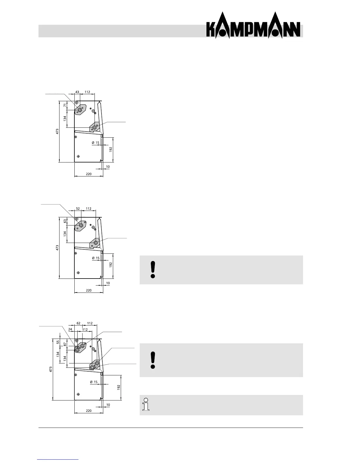
6.9 Connection to Pipework (for units with or without customer‘s valves)
Vorlauf 1/2“
Heizen
Rücklauf 1/2“
Heizen
Rücklauf *
Kühlen
Vorlauf *
Kühlen
Vorlauf *
Rücklauf *
Vorlauf *
Rücklauf *
Fig. 36: Dimensions of pipe
connections
2-pipe, 3-row
2-pipe, 4-row
4-pipe, 4-row
Flow
Flow
Flow 1/2“
Heating
Return
Return
Flow *
Cooling
Return *
Cooling
Return 1/2“
Heating