49
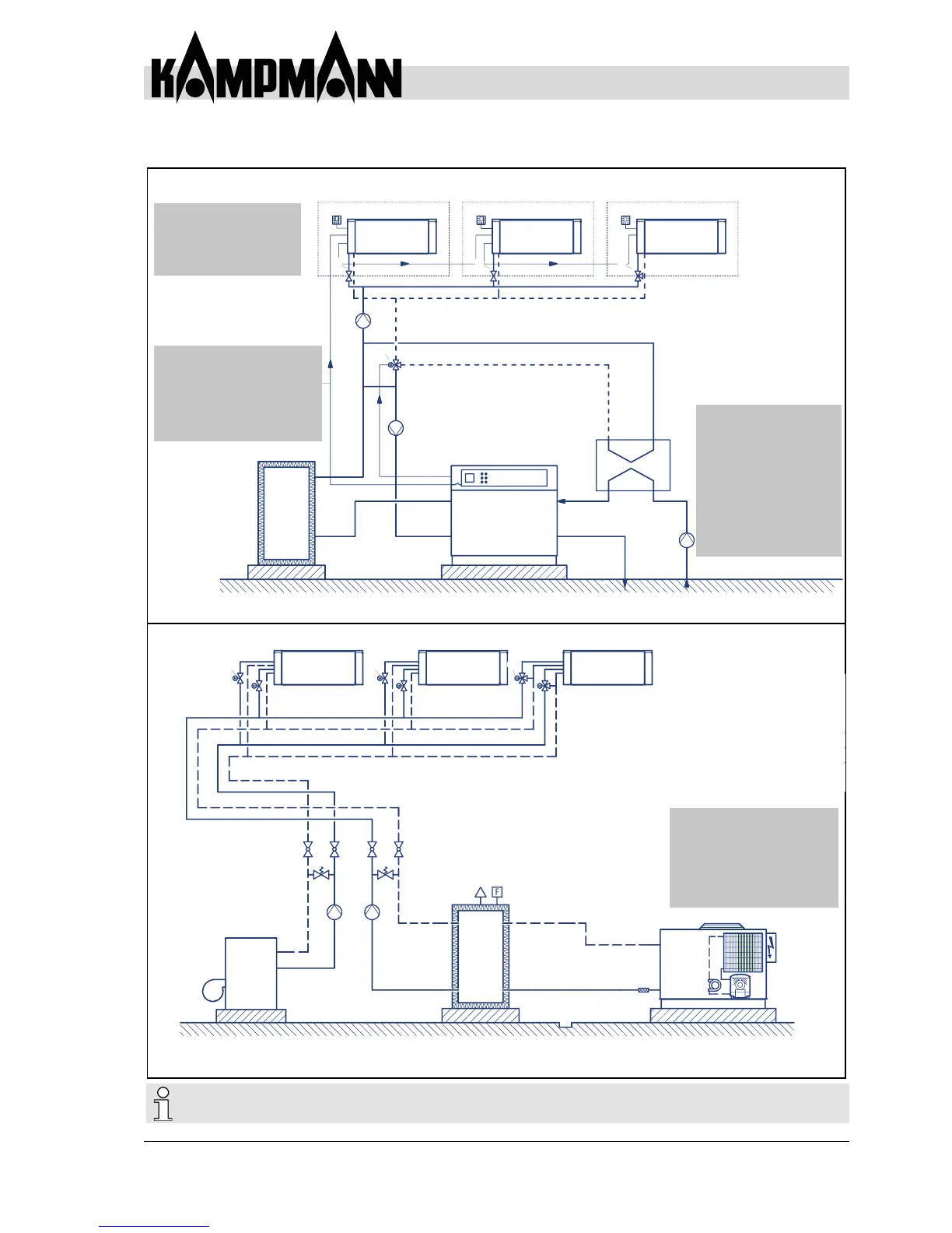
Installation and Connection
2-pipe / 4-pipe system
2-pipe system (heating or cooling)
4-pipe system (heating and cooling)
Fig. 34: Design example
4
2
1
3
6
7
5
4
2
1
3
6
7
8
5
•
Minimal pipework; only
two pipes (ow and return)
needed
•
Central heating/cooling
changeover
•
Especially suitable for smaller
to medium systems or where
only cooling or heating is
required
•
Four pipes (ow and return for
both heating and cooling) are
routed to the fan coil
•
Primarily suitable for larger
systems, where there are overlaps
between heating and cooling
(north and south side)
1
Water/water heat pump
2
Buffer tank
3
Circulation pump
4
Changeover valve (heating/cooling)
5
Plate heat exchanger
6
2-way control valve
7
3-way control valve
1
Boiler
2
Buffer tank
3
Chiller
4
Heating circulation pump
5
Chilled water pump (consumer circuit)
6
Relief valve
7
2-way control valve
8
-way control valve
Fig. 35: Design example
3
6
3
Room 1 Room 2 Room 3
6
7
Heating/cooling
changeoverfunction:
Heating/cooling changeover by the
heat pump control. The heat pump
provides a potential-free contact for
the fan coils.
Monovalent heat pump
operation or a water/hot
water pump and dynamic
cooling by fan coils
Please note the relevant standards and directives relating to the hydraulic installation
(e.g. on-site hydraulic balancing and shut-off devices).