55
Operation
Condensation pump
The water is drawn off by the condensate pump and discharged
along a hose (supplied loose) connected on the pressure side.
Depending on conditions on site, the water can be discharged into
drainage lines, possibly with a trap connection.
Aoatswitchmonitorsthewaterlevelandswitchesthepumpoff
if it is exceeded. The condensate is drained off. In the event of a
fault with the condensate drain, the water level will continue to rise
untiltheoatswitchtriggersanalarmcontact.Thecontactcanbe
analysed by external signalling devices.
We would recommend automatically terminating cooling operation,
possibly with a shut-off valve, if the alarm contact is triggered to
preventthecondensatetrayfromoverowing.
Condensate drain (accessory)
• Drainage of condensate from the condensate pump has to be
provided along a natural gradient with an adequate cross-section
(minimum 1/2“). Increase the cross-section of the line with longer
condensate lines.
• Check whether the condensate line needs to be insulated to prevent
the build-up of condensate along the line.
• Do not use a rigid transition to the on-site condensate drain, as this
lengthens the pump‘s pressure hose. We would recommend free
overflow into a trap.
• Refer to chapter 6.11 on page 53 for further information on
condensate drainage.
Installation of the condensate pump (accessory)
Cabling
The condensate pump needs a separate power supply (230
V/50 Hz). We would generally advise against connecting it via the
room thermostat, as residual condensate could be produced after it
has been switched off. Additional wires are needed to analyse the
alarm contact.
Usethefollowingtypesofcable:
Mainssupply:NYM-J,1.5mm
2
Alarm contact The cable for the alarm contact depends on the kind
of alarm analysis used (e.g. shielded cable).
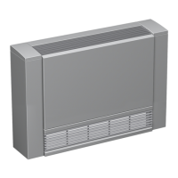
Fig. 45: Position of condensate pump
on wall-mounted unit
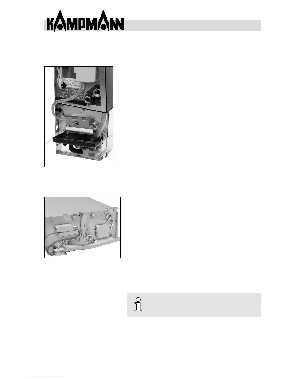
Fig. 46: Position of condensate pump
on ceiling unit
Carry out an initial service on the condensate
pump and oat switch directly after
commissioning.
6.13 Condensate Pump