59
Operation
Controls Overview
6.16 Controls Overview
Kampmann fan coil units come in a series of different versions.
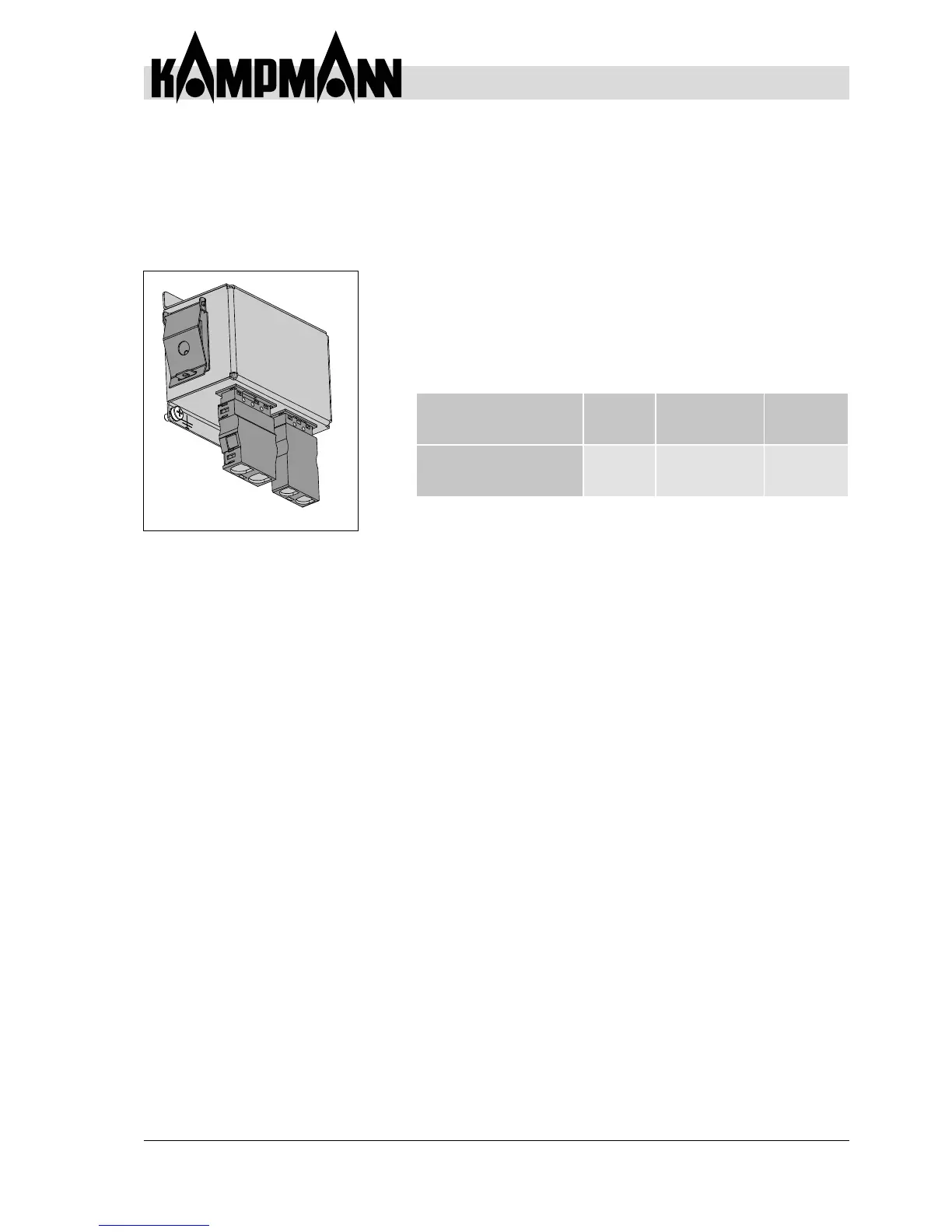
The fan coil components are connected via a terminal strip. This
is located in a terminal box, mounted on the opposite side to the
water connection on the basic unit (see Fig. 48).
• The fan coil unit is available as a wall-mounted, ceiling or free-standing
unit in conjunction with a controller.
• Wire the unit as per the wiring diagram, which is different for each
version.
Model
Control
option
Connection
Wiring
diagram
(CAD no.)
electromechanical
without motor fault alert
E00
On-site control
(BMS)
12396
Fig. 48: Junction box 115 V