48
48
Installation and Connection
Hydraulic Connections
6.8 Hydraulic Connection
DesignfortheuseofunitsoperatedwithCHW:
-Thedimensionsofthesystemmayneedtobemodied.The
water volume is generally higher than with heating networks.
The normal temperature spread is around 6 K.
- Hydraulic shortcomings by the design, choice of distributor
system and poor hydraulic balancing are much more
noticeablethanwithhotwatersystemsandaredifcultto
detect and correct.
- The effective outputs have to be precisely tailored to actual
conditions of use. Take into consideration the possible rise
in temperature of the cooling medium, particularly along
longlengthsofpipework.(Forexample:Temperatureat
the generator 6/12 °C, temperature at the consumer 8/14 °C,
therefore loss of output)
- Check the suitability of all components (such as circulation
pumps etc.) for the use of CHW, noting the minimum
temperatures.
- The addition of anti-freeze has an adverse effect, for instance
it reduces cooling output at the generator and consumer
by impairing heat transfer / higher pressure losses in the
pipework by the lower viscosity of the cooling medium; the
consequenceishigherpumpcapacity:
Design: Notethefollowingpointsinthedesign:
- Fit end-to-end, vapour-impermeable insulation on all water-
carryingcomponents(pipes,valves,ttings)rightuptothe
unit (ensuring that the insulation goes as far as the disc under
the valves and ensuring that the insulation is adhered by the
condensate tray to the drip plate).
- Select suitable pipe brackets for cooling mode (chilled clamps)
- Install and check safety-related components (e.g. expansion
tanks,reliefandoverowvalves)
-Allowadequatespacefortheairow(airinletandoutlet)
-Positioncoolingunittotinwithttingsandinterior
architecture
- Make sure that any condensate produced can drain
away freely; check the free area of the condensate drain
connection/run condensate line along a gradient, without
bends or restrictions, to the on-site waste water line
- Size dimension of condensate line appropriately
-Protecttraps(iftted)inthecondensatelinefromdryingout
(possibly by the use of a ball trap)
- Use condensate pumps, noting the maximum delivery height,
if there is no natural gradient
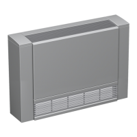
Fig. 32: 2-pipe system:
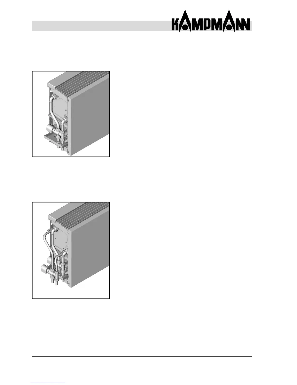
Fig. 33: 4-pipe system: