43
Installation and Connection
Installing the Basic Unit
6.4.2 Ceiling Basic Unit
Allow for minimum clearances to any on-site resistance when
installing (see Chapter 6.2).
Keyholes are provided at the top and bottom of the rear panel for
installation of the basic unit (Fig. 19).
Mark drill holes (spacing of keyholes) on the ceiling as per Fig. 19 and
adjacent table and then drill holes.
Use suitable xing material depending on the type of ceiling
mounting.
Fitxingmaterialintotheceiling.
Suspend basic unit on the 4 keyholes.
Leveltheunitforperfectoperation.Intheeventofcondensate,t
the unit with a 1.5% gradient towards the condensate discharge side.
Oncethebasicunithasbeenaligned,preventthexingmaterial
from coming loose.
Provide for sound isolation between the fan coil
and the adjacent building if required.
Cam locks can be used on site for simple height
levelling.
Allow for minimum clearances to any on-site resistance when
installing (see Chapter 6.2).
2standingbracketsarefactory-ttedonthebasicunit.Usesuitable
xingmaterialtoxthemandthebasicunittotheoor.The4key
holes on the rear panel of the base unit are unused.
Markdrillholes(spacingoflongitudinalholes)ontheoorasper
Fig. 21 and adjacent table and then drill holes.
Usesuitablexingmaterialdependingontheoorcovering.
Fitxingmaterialintotheoor.
Align for correct and proper operation of the basic unit (note
condensate drain if necessary).
Oncethebasicunithasbeenaligned,preventthexingmaterial
from coming loose.
Provide for sound isolation between the fan coil
and the adjacent building if required.
6.4.3 Free-standing Basic Unit
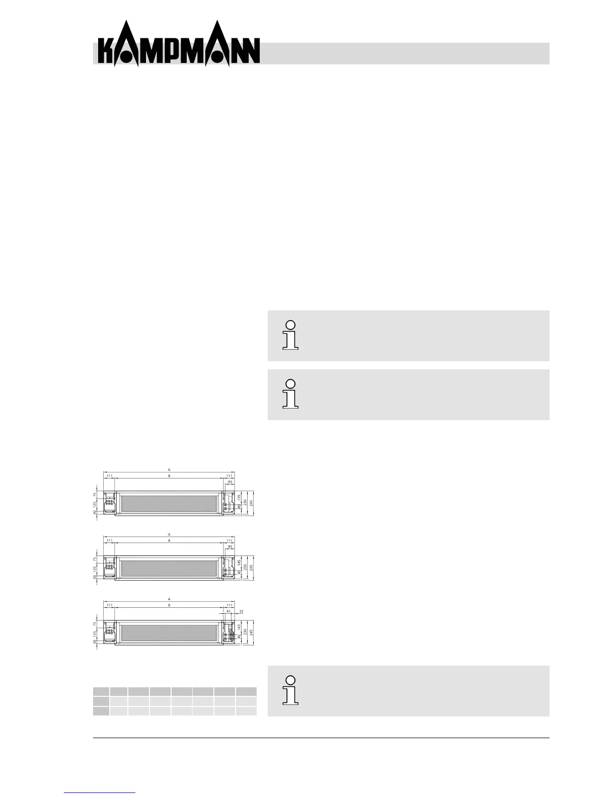
Fig. 21: Dimensions for oor xings
and connections
Mod
1 2 3 4 5 6 7
A 850 1000 1150 1300 1450 1600 2000
B 628 778 928 1078 1228 1378 1778