4242
Installation and Connection
Installing the Basic Unit
6.4 Installing the Basic Unit
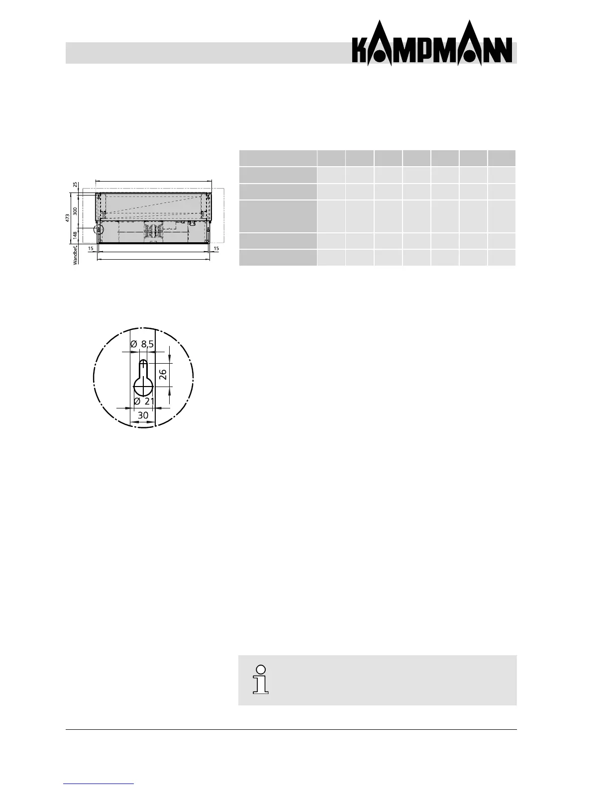
Basic unit dimensions and spacing of keyholes (per size)
Selectxingmaterial(e.g.boltsanddowels)onsite.
6.4.1 Wall-mounted Basic Unit
Allow for minimum clearances to any on-site resistance when
installing (see Chapter 6.2).
Keyholes are provided at the top and bottom of the rear panel for
installation of the basic unit (Fig. 19).
Mark drill holes (spacing of keyholes) on the wall as per Fig. 19 and
adjacent table and then drill holes.
Fitxingmaterialtothewall.
Suspend basic unit on the 4 keyholes.
Leveltheunitforperfectoperation.Intheeventofcondensate,t
the unit with a 1.5% gradient towards the condensate discharge side.
Oncethebasicunithasbeenaligned,preventthexingmaterial
from coming loose.
Provide for sound isolation between the fan coil
and the adjacent building if required.
Mod 1 Mod 2 Mod 3 Mod 4 Mod 5 Mod 6 Mod 7
Main condensate tray
[mm]
620 770 920 1070 1220 1370 1770
Rear wall [mm] 590 740 890 1040 1190 1340 1640
Wall mounting
[mm]
(Spacing between the
suspension points)
560 710 860 1010 1160 1310 1610
Number of motors 1 1 1 1 1 1 2
Number of fans 1 1 2 2 2 2 4