Page
83
9
Appendix
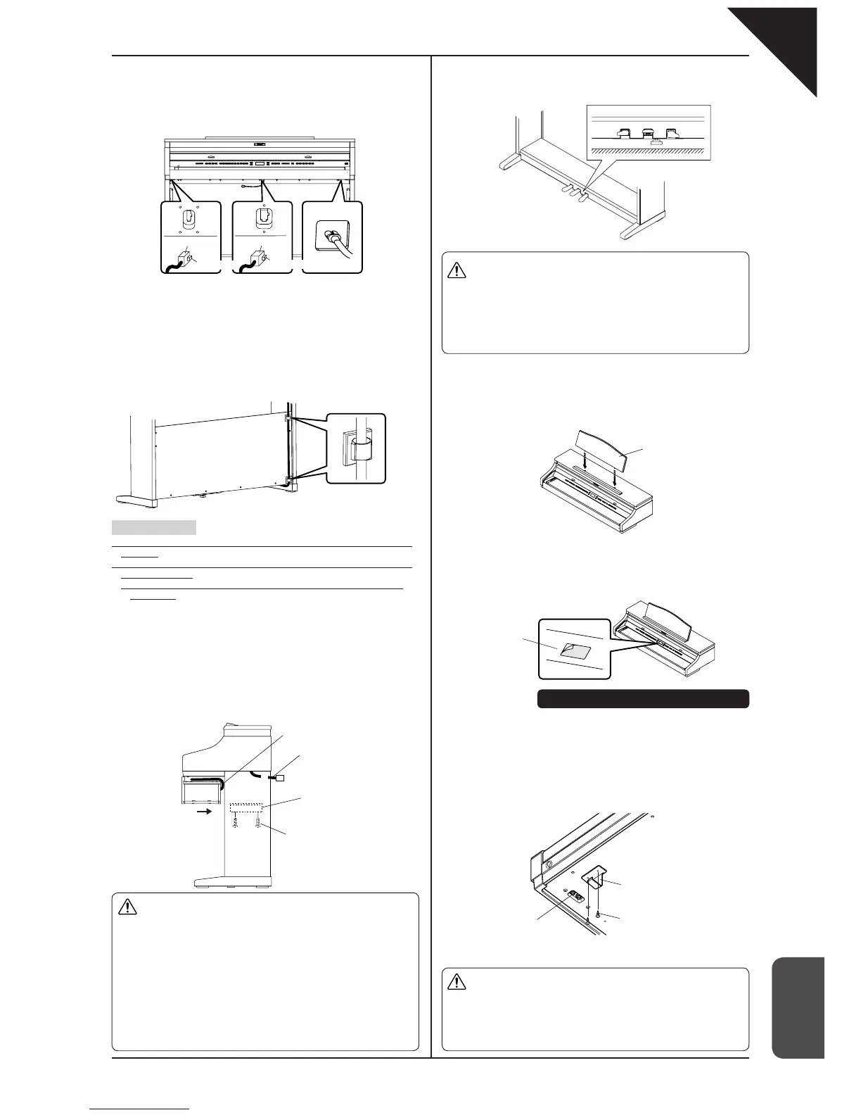
4. Connecting the cords (select method A or B).
A. When the cords are placed in the side panels:
(1) Connect the pedal cord and the power cord to the piano.
(2) Connect the relay cord to the piano. Place the other end of the relay
cord at the backside of the back panel.
Attaching the headphone hook
Using two screws with a sharp end (
φ
4 x 14) that come with the Headphone
hook, you can attach the headphone hook beside the headphone jack.
This step is optional. If you do not need the hook, keep it with the
instruction manual.
5. Attaching the speaker box.
(1) Place the speaker cord over the top of the speaker box.
(2) Place the speaker box on top of the metal brackets on the side panels,
and align the threaded holes.
(3) By using screws A with a fl at end (M6 x 25), attach the side panel.
(4) Pull the speaker cord towards the backside of the back panel, and
connect it with the relay cord.
(5) Place both the speaker cord and the relay cord between the speaker
box and the back panel.
6. Adjust the pedal support.
Turn the pedal support (E) at the bottom of the stand until it reaches the fl oor.
B. When the cords are not placed in the side panels:
(1) Connect the power cord and place its other end at the backside of the
back panel.
(2) Connect the pedal cord from the backside of the back panel.
(3) Fasten the pedal cord with the cord clamp.
(4) Connect the relay cord to the piano.
Place the other end of the relay cord at the backside of the back panel.
* This is not necessary when the cords are placed in the side panels.
Important point:
· Make sure that the locking tab of the connectors is facing the correct
direction.
· Insert the connector straight. Do not apply too much force; it may
cause unit failure.
* To pull out the cord, remove the connector while pressing the
locking tab.
7. Check the screws.
Confi rm that all the screws are properly tightened.
8. Attach the score stand.
9. Remove the protective plastic fi lm on the display.
Connector
Locking tab
Connector
Locking tab
Pedal cord Relay cord Power cord
* This is not necessary when the
cords are placed in the side
panels.
Speaker cord
Relay cord
Metal fi ttings
Screws with a fl at end
A. M6 x 25
Score stand
Display
Assembly is now complete
Headphone jack
Headphone hook
Screws for attaching the
headphone hook
Caution
x
Make sure that more than two people work on unit
assembly.
x
Make sure that your hands are not caught between
the speaker box and the stand when placing the
speaker box.
x
Use the screws provided in order to securely fasten
the speaker box to the stand. Failure to do so may
result in the speaker box falling off from the stand,
causing great danger.
x
Do not force the screws in. Insert them straight into
the hole without excessive force and tighten them
there.
x
Lightly tighten the screws by hand fi rst to make sure
that they are threaded correctly.
Caution
<When moving the unit>
x
When you move the unit, make sure to remove the
end panels and the pedal support before moving.
x
Do not drag the unit.
x
When you remove the piano part from the stand, fi rst
disconnect the pedal cord, speaker cord, and power
cord.
x
The pedal stand may be damaged if the pedals are
used when the pedal support is not touching the fl oor.
make sure that the pedal support is touching the fl oor.
x
Once the pedal support touches the fl oor, stop turning
it. Failure to do so may result in damage to the stand.
x
When you move the unit, remove the pedal support
before moving. Readjust the pedal support after
moving is complete.
Caution