Chapter 1. Setting Up the RF ValProbe
6 RF ValProbe® User’s Manual
1.1.5 Kaye RF ValProbe Temperature/Humidity Loggers (cont.)
You can attach auxiliary inputs (contact, voltage or current) into the socket on top of the
probe. If you select a Logger model with an external probe, the probe is attached to the
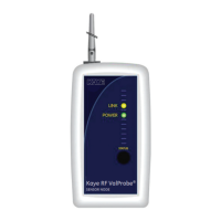
Logger through an outlet on the side. To turn the Logger on, slide the power switch
(shown in Figure 4 on the next page) to the right.
Two LEDs — the green Power and the yellow Link light — indicate Logger status.
• When you press the Status button, the green Power light appears to show that the
Logger is receiving sufficient power. (To use the Status button and Power signal to
reset battery capacity, go to page 8.)
• The yellow Link signal passes through four stages as a user presses and holds the
Status button:
1. Its initial signal is a slow blink before it attempts to connect to the network.
2. The blink becomes more rapid as the Logger scans the area for a network (Base
Station or Logger) connection.
3. A double blink indicates that the Logger has linked and is transmitting, either to
another Logger or to a Base Station.
4. Finally, a solid yellow light indicates that the Logger has made two separate
connections (the maximum possible for a Logger) to the network.
Note: In a given network with more than one Logger, there will always be one Logger
that has only one link, and consequently stays at the double blink stage.