D3DA3xx/x Appendix
ProjectengineeringmanualV1.00
105
©KEBA
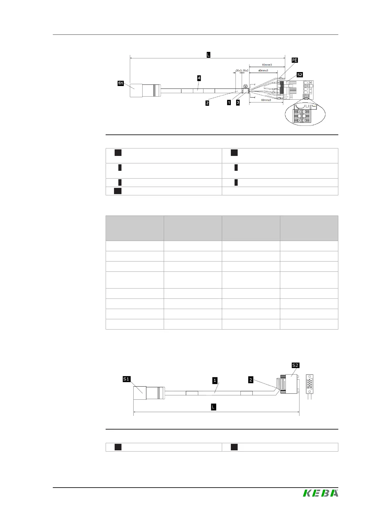
Illustration1551:StructureoftheconnectioncableXWH0xxxx
S1 ...Connectormotorsided S2 ...Connectordrivecontrolsystem
sided
1 ...Outerandinnershieldsconnected
tocopperstrip
2 ...Shrinkingtubeoverlapsthecopper
strip(5mm)
3 ...Shieldisfixedatthemountingplate 4 ...CableoflengthL
PE ...Notconnected
PinassignmentatconnectioncableXWH0xxxx
Signal
ConnectorS1
(Motorsided)
Colorofwires/
identification
ConnectorS2
(Drivecontrol
systemsided)
U 1 Black,whiteimprintU U
PE 2 Greenyellow n.c.
V 3 Black,whiteimprintV V
W 4
Black,whiteimprint
W
W
HDSL+ A White 2
HDSL B Brown 1
Br+ C Black,whitefigure5 3
Br D Black,whitefigure6 4
15.2.3 SignalcableXWE10xxx
Illustration1552:StructureofthesignalcableXWE10xxx
S1 ...Connectormotorsided S2 ...ConnectorHDSUB

 Loading...