2400 Series SourceMeter
®
User’s Manual Contact Check Function F-3
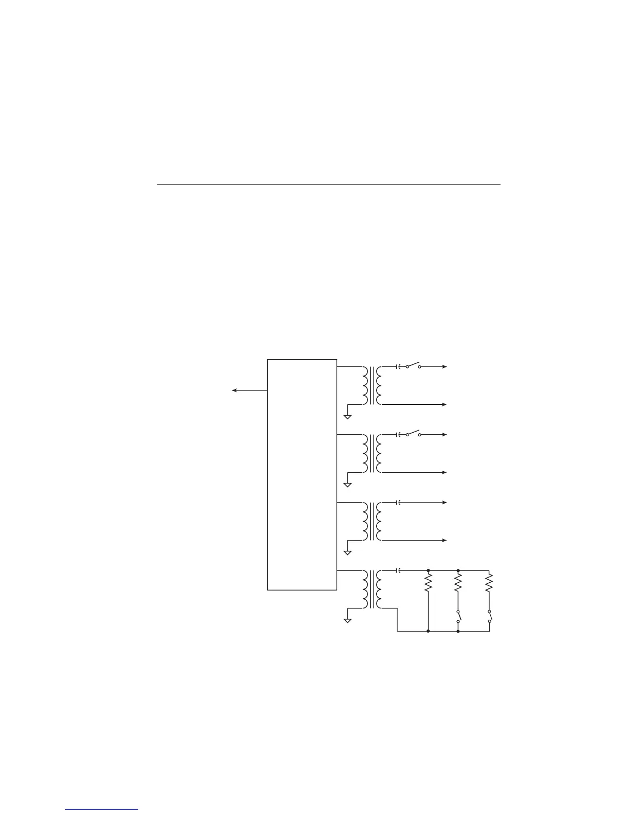
Block diagram
A block diagram of the contact check circuitry is shown in Figure F-2. The microproces-
sor sends a contact check pulse that is amplified to drive the primaries of four transform-
ers. The secondaries of transformers T1 through T3 drive a force/sense contact pair for HI,
LO, and GUARD. (HI Force and LO Force are switched through S1 and S2.) The trans-
formers provide isolation among the inputs. Capacitors C1 through C3 in the secondaries
provide a high resistance DC path but low resistance AC path between the force and sense
leads. Transformer T4 drives the trip point resistor(s), R
SET
. If the resistance in any of the
DUT connections exceeds the value of R
SET
, it is considered an OPEN LEAD condition
and the microprocessor is notified. Note that the trip point resistance (R
SET
) can be
changed by closing either switch S3 or S4, resulting in 2Ω, 15Ω, or 50Ω threshold resis-
tance values.
Figure F-2
Contact check block diagram
HI Force
C1
T1 HI Sense
LO Force
C2
T2 LO Sense
Guard Force
C3
T3 Guard Sense
C4
T4
To
Microprocessor
Pulse Amplifier
Signal Comparitors
Timing Generator
Computer Interface
R
set
50Ω
R
setA
22Ω
R
setB
2.1Ω
S1
S2
S3
S4
Artisan Technology Group - Quality Instrumentation ... Guaranteed | (888) 88-SOURCE | www.artisantg.com