Refer to the Kern website link http://www.kernlasers.com/pw/login.htm for system setup videos.
Safety eyewear must be worn during the setup process. Two sets of laser safety glasses are included
with the laser system. The recommended setup and operational testing is as follows:
Description
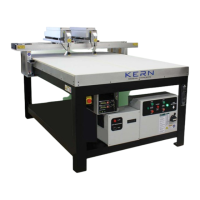
The DHS machine consists of a rectangular frame that is constructed from heavy angle section steel.
The frame has four uprights on each corner, which act as legs. These support a worktop tray that is
made of steel plate. The tray has a flat base and is welded on top of the legs. There are ribs that run
the full length of the worktop tray and stiffen the tray. These are structural members and are deep
enough to create a plenum for the extraction of dust or toxic fumes generated during engraving or
cutting operations. Aluminium ecolite and honeycomb grid layers form the worktop. Two flexible
ventilation hoses are connected to the end of the worktop tray and these are used to place the tray
under vacuum. A blower is provided to create a vacuum and collect dust and toxic fumes. Worktop
grids are designed to suit the various materials that can be cut or engraved by the laser system.
Materials to be cut or engraved must be flat to within 1 mm to 2 mm. This flatness will ensure that
the material will be held under vacuum. Crossbeams run between the legs at a lower level. These
are positioned above floor level and are covered by flat plates on three sides. The flat plates receive
the control system enclosure and a DC power supply and guide a cable chain conduit.
A gantry runs above the grids and spans the full width of the tray. The gantry is able to travel the
full length of the worktop tray. The gantry has two vertical columns at each end. These are
connected to a flat plate that runs in a clear space underneath the worktop tray. A linear bearing
block is mounted on top of this plate at each end. The bearing block is specially shaped and each
block runs along guide rails that are secured to the underside of the worktop tray. The gantry is
connected to a lead screw and a drive belt connects the lead screw to a servo motor. The servo
motor is mounted to the underside of the worktop enabling the gantry to be traversed in the X axis.
The lead screw has a spring loaded anti-backlash nut that is mounted on the underside of the gantry
and is manually lubricated with lithium grease. The lead screw runs in bearings blocks, one at each
end of the worktop, and these must also be lubricated manually using lithium grease.
The front of the gantry carries an optical head that travels the full width of the worktop tray. The
optical head consists of a laser tube containing a lens, a means of injecting an assist gas that is used
to keep the lens clean and an optical nozzle. The optical head is optically connected to a laser
source. The optical head is mounted on a carrier that runs the full width of the gantry. Linear bearing
blocks are mounted on each side of the carrier. The bearing blocks are specially shaped and run in
guides on each side of the carrier. The guides are bolted to the gantry frame. A timing belt that is
operated by a servo motor moves the carrier. The timing belt runs around sprockets and is
connected to the carrier on one side. The shaft of each sprocket runs in a bearing block, one at each
end of the gantry. This enables the carrier to be traversed in the Y-axis.
The optical head moves in a vertical plane and is guided by four guide rods that are supported by the
carrier. The optical head is connected to a lead screw and a timing belt connects the lead screw to a
servo motor. The servo motor is mounted on the carrier enabling the optical head to be traversed in
the Z-axis. The lead screw has a spring loaded ant backlash nut that is mounted on the side of the
optical head and is manually lubricated with lithium grease. The lead screw runs in bearings at the
top and bottom of the carrier and these must also be lubricated manually using lithium grease. Two
limit switches are used to determine when the optical head has been driven to its maximum upper
and lower limits of travel.
The top of the gantry carries a CO
2
laser source. The laser source is excited by a DC RF power
source. On water cooled models, the RF source must be water cooled. A chiller provides cooling
water and must be set to operate at a temperature of 20 to 21°C (68 – 70 °F). The HSE machine
must not be operated in a room at a temperature in excess of 27 °C (80 °F).
The laser is first directed at a collimator. In the case of 150 watt lasers the beam is passed through a
beam shaper. On leaving the collimator the beam is directed at a mirror that turns the beam through
8