Unplug the DC power supply plug from the outlet underneath the laser table. Plug the laser harness
into the connector on the back of the laser.
The laser is now installed and is ready for beam alignment. Reconnect the DC power supply plug
underneath the laser table before powering up the system.
Chilling Unit
All laser systems of 100 watts or greater will come with a chilling unit for cooling the laser. The
chilling unit will automatically turn on and off with the main power of the laser system. Please review
the chiller’s Operators Manual before setting up the chilling unit.
100, 150 & 200 Watt Systems
1. Remove the chiller from its box and place next to the rear of the laser system.
2. Hook up the water lines from the laser system to the back of the chiller. The water lines
should be labeled for connection to the correct inlet/outlet fittings.
3. Fill the tank with a 1/2 gallon of propylene glycol and top off with distilled water.
4. Connect the power plug into its labeled outlet on the back of the laser system.
5. Verify that the circuit breaker on the back of the chiller is in the ON position.
6. When the system is first powered up, verify that no leaks are present at any of the water
line fittings or along the water lines.
7. Refer to the laser’s Operator Manual for proper cooling fluid temperature.
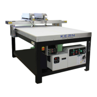
Electrical Panel
The electrical panel in the front of your laser system must be hooked up by a certified electrician.
Failure to follow through will void the system warranty. The main power cable is not included and
should be available from your certified electrician. A complete panel schematic is located inside of
the electrical panel. This schematic is strictly to assist the electrician. If a schematic cannot be
found, please contact Kern for a copy.
Air/Assist Gas
Connect 60-95 PSI of clean, dry air from an air compressor to the air quick connector located on the
back of the laser system. Air must be filtered before it reaches the laser system for both oil and
water. Recommend 5 micron pre-filter and 0.1 micron filter. Connect optics and knife air tubing to
optics assembly.
Recommended air supply volume is 3 CFM with a 20 gallon reserve tank.
For metal cutting, assist gases such as oxygen and nitrogen may be used. Use the same connection
on the back of the system for connection of these gases as well. A regulator will be needed on the
gas tanks and allow for up to 150 PSI of pressure.
Must use separate air lines for compressor air and oxygen/nitrogen to back of laser system.
Vacuum System
Blower Electrical Connection
The blowers included with the laser system operate on 230 volts AC. All HSE systems have power
outlets on the back for connection of the blowers. The blower operation can then be controlled from
the main electrical panel for the laser system. If blowers of different sizes (horsepower) are used,
the electrical outlets may be labeled for proper connection.
14