4. Use the lens removal tool to unscrew the top lock ring.
5. The lens is now exposed and can be carefully removed by holding it by the sides only. Set
the o-ring to the side. Use a clean rag or rubber gloves to carefully remove the lens. Avoid
touching the front and back surface of the lens. Check for any scratches, pits and blemishes.
The lens will have a yellowish color to it without any cracks or blemishes. It is very important
for the optics to be clean. If a lens has blemishes or damage, cleaning of the optic may not
repair the damage.
NOTE: The lens may appear clean in the assembly, but may still be dirty. The lens must be
taken out to check for cracks and blemishes.
To clean a lens:
1. Remove visible debris from the lens using a Q-tip soaked in isopropyl alcohol or rubbing
alcohol (90% alcohol based).
2. Flush the lens with 99% isopropyl alcohol.
3. Using a lens tissue soaked in isopropyl alcohol, wipe the optic lightly in a circular motion.
4. Repeat step 3 with a new lens tissue. The isopropyl alcohol dries very quickly. The surface of
the optic should be clean and spotless when cleaning is finished. If blemishes on the optic
will not clean off, a replacement optic should be purchased to achieve optimum laser cutting
and engraving performance.
To reinstall the lens after cleaning:
1. Carefully place the lens back in the optics assembly on top of the o-ring. The convex side of
the lens must be facing upwards as it is placed back in the optics assembly.
2. Screw the black lock ring back into the assembly using the lens tool.
3. Reinstall the optic assembly back into beam path tube.
4. Reconnect the air line, shroud and the HF sensor wire (if present).
NOTE: It is recommended to do a beam alignment through the nozzle after you reinstall the
lens.
Lead Screw Nut Adjustment
Please consult the factory before removing and cleaning the nut.
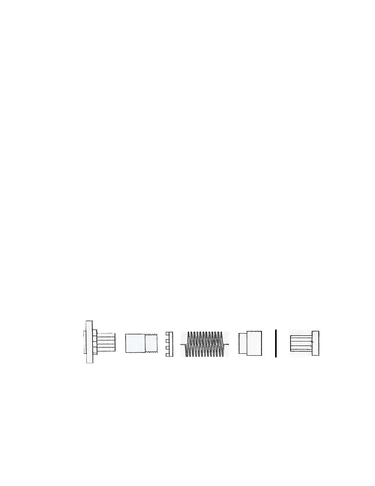
1 2 3 4 5 6 7
Lead Screw Nut Assembly
1. Mounting Body
2. Inner Body Spline
3. Spring Adjustment Collar
4. Spring
5. Spacer Nut
6. Rubber Washer
7. Rear Body
60