Chapter 1: Installation and wiring
P/N 3102351-EN • REV 005 • ISS 28DEC18 31
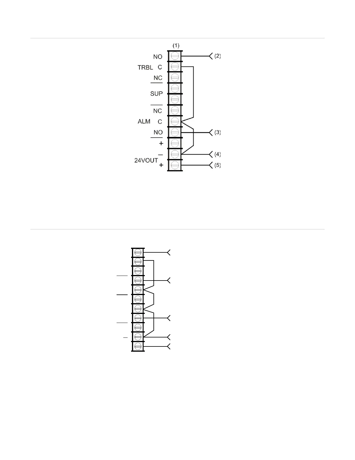
Figure 42: Alarm and trouble transmitted on a single circuit
2) From TRBL on RPM (yellow wire)
(3) From ALRM on RPM (brown wire)
(4) From COM on RPM (black wire)
(5) From +24 on RPM (red wire)
Note: JP1 on the RPM must be OUT.
Figure 43: Alarm, supervisory, and trouble transmitted on separate circuits
2) From TRBL on RPM (yellow wire)
(3) From SUPV on RPM (orange wire)
(4) From ALRM on RPM (brown wire)
(5) From COM on RPM (black wire)
(6) From +24 on RPM (red wire)
Note: JP1 on the RPM must be IN.
From ALRM on RPM (brown wire)
From TRBL on RPM (yellow wire)
From COM on RPM (black wire)
From +24 on RPM (red wire)
From SUPV on RPM (orange wire)
Control panel
TB3
TRBL
C
NC
SUP
NC
ALM
24VOUT
+
NO
C
NO
+