63
Application
diagram
symbol
Description
Cable
type
No. of
conductors x
cross section
[mm
2
]
B4
Air exhaust temperature sensor downstre-
am heat recovery
LIYY* 2x1
B5 Optional master temperature sensor LIYY* 2x1
B8
Optional sensor for the heater’s return
water (absent in systems with a primary
heater)
LIYY* 2x1
1S1F Air supply fan dierential pressure gauge LIYY 2x1
1S1H
Air supply preliminary lter dierential
pressure gauge
LIYY 2x1
1S2H
Air supply secondary lter dierential
pressure gauge (optional)
LIYY 2x1
2S1H
Air exhaust preliminary lter dierential
pressure gauge
LIYY 2x1
2S1R
Cross-ow heat exchanger’s pressure gage
in system with HPM
LIYY 2x1
E5 Start conrmation – voltage-free contact LIYY 2x1
N3
Programming device HMI Advance,
2 cables: communication – BUS,
power supply – LIYY (max 100m)
BUS O2Y-
S(St)CY
1x2x
0,64/2,6
LIYY 2x1
*) In case of facilities with anticipated high level of cable interferences, voltage induct-
ance, please use LIYCY-type cables.
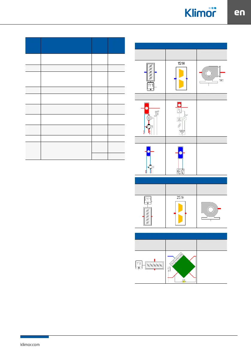
Table No 10 The legend for standard EVO-T control cabinet application diagrams:
AIR SUPPLY PART
Air supply (fresh)
damper
Air supply preliminary
lter
Air supply fan
Water heating coil Electric heater
Water cooling coil DX cooling coil
AIR EXHAUST PART
Air exhaust (extracted)
damper
Air exhaust lter Air exhaust fan
COMMON PART OF AIR SUPPLY AND AIR EXHAUST
Mixing, recirculation
chamber’s damper
Cross-ow recovery -