65
Table no. 13 List of relay outputs
Relay outputs, switched o state – ReC/ReA output open,
switched-on state – ReC/ReA output shorted*
Re1 Water heating coil pump
Re2
Ice water unit for water cooling coil
DX cooler, stage I
Re3 DX cooler, stagel II
Re4 Air supply/exhaust dampers
Re5 Electrical heater
Re6 Operation signal of additional fan
Table no. 14 List of analog outputs
Analog output (0÷10VDC signal output)**
Aout1 Heater (water or electric), preliminary or secondary
Aout2
Cooling coil (water or electric cooling coil equipped with dedicated
power supply module)
Aout3
Mixing chamber (10-0V), air supply/exhaust dampers (0÷10V) or
heat/cool recovery (cross-ow)
* Possible negation of digital input in Settings/DX cooler menu.
** In the service menu you can select one of the analog outputs as the 0÷10V signal of air
supply fan exhaust fan.
8. CONTROL OPERATION
8.1 Starting-up the system
Turn the Q1M trip switch into ON position:
CG EVO-T (COMPACT) 2S CG EVO-T (COMPACT) 4S
Fig.
3 Control cabinet switches
After power cut-o, the system automatically
resets to the settings operating before the power
cut-o.
The system is started, if:
• There is no alarm blocking system operation
• “S1F – re alarm” signal is shorted at the controller DIN1
input and “Set operation mode” parameter at the con
-
troller or programming device is set to any other option
than Stop.
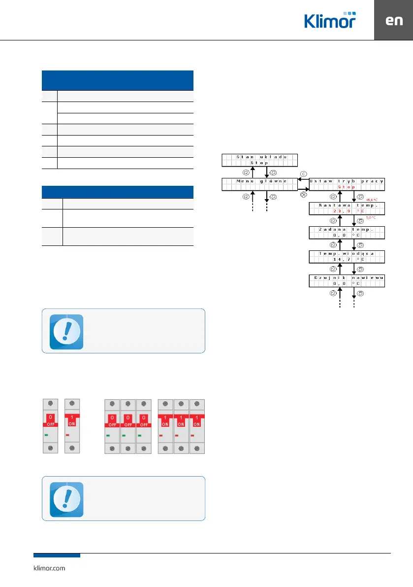
8.2 Changing set temperature
NOn the controller or programming device in the main
menu, “Temperature settings” parameter.
Fig.
4 Changing set temperature
Changing operating mode:
Press OK button. “Stop” starts blinking. Switch to anoth
-
er mode and conrm with OK button.
Changing the temperature setting:
Press OK button “23.9..” starts blinking. Switch to anoth
-
er value and conrm with OK button.
8.3 Standby mode
In order to save energy the control system is able to oper-
ate in standby mode. Select this mode using “Operation
mode” setting in the main menu of the controller or in
the calendar. Depending on the requirements it is pos
-
sible to set the standby mode only for heating, only for
cooling or both for heating and cooling (see point 9.3).
Below there is a description of system reaction when
switching from the operation into standby mode
(heating).
System I – system is stopped,
System II – system is switched on for operation, fans and
heat/cool exchanger are started, master temperature is
adjusted (in this case Tsup – air supply) up to the set tem
-
perature 22°C
System III – the system is stopped, supplied air tempera
-
ture and room temperature is decreasing.
Before the user starts the system, the control
cabinet shall be connected and checked by the
authorised personnel.