66
AUTOMATION AND CONTROL SYSTEM FOR UNITS EVO-T; EVO-T COMPACT
OPERATION AND MAINTENANCE MANUAL
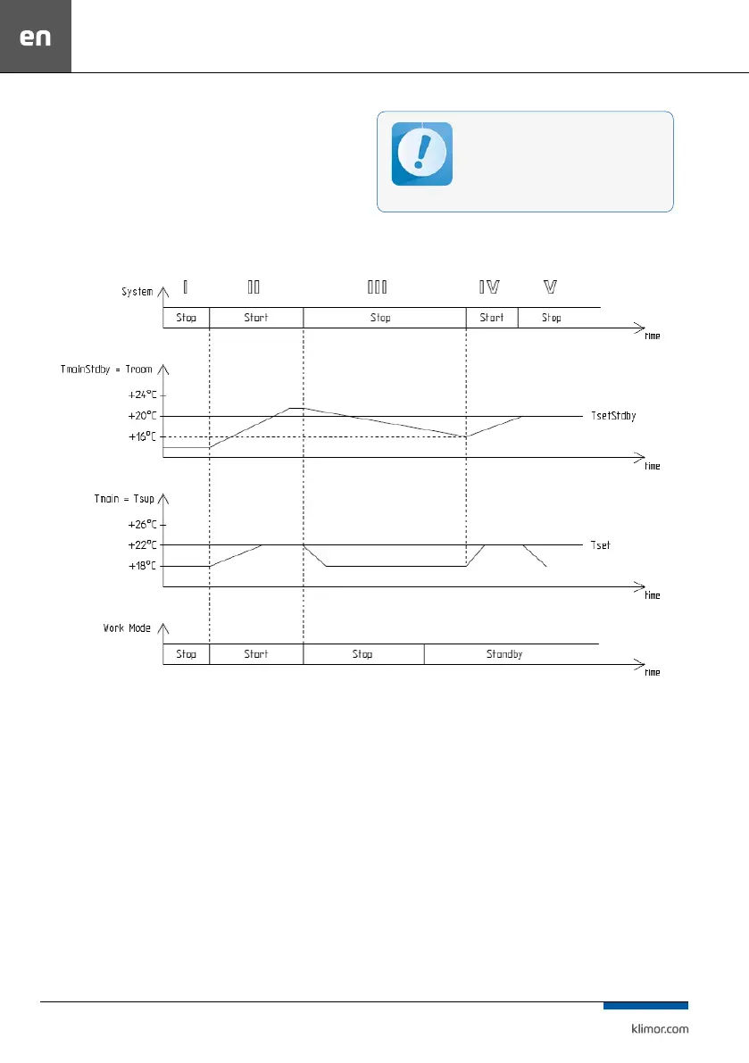
System IV – the system is switched on for operation be-
cause the switch-on conditions have been reached, ie. de-
crease of standby mode master temperature (in this case
Troom – room temperature) by the hysteresis value of 4°C,
from the set value TsetStdby of the standby mode = 20°C,
the temperature adjustment of the AHU is carried out
against the master sensor (in this case Tsup – air supply).
System V – the system is stopped because the standby
mode set temperature has been reached (Troom = Tset
-
Stdby).
Fig. 5 Controller operations in the standby mode
For correct system operation in the standby
mode it is recommended to use an additional
room temperature sensor (connected to the
PT5 input) located in a representative room.
You can also use the HMI panel for this purpose.
Readings of air supply and exhaust tempera-
ture sensors in this mode can be unreliable.
8.4 Alarms
Alarms are indicated by the display blinking and by red
LED on the controller or programming device as well
as by switching on a rely output of the Re8 controller.
Alarm description can be found in the “Alarm menu”.
Hold “C” key for about 3 seconds to access the Alarm
menu. The last position in the alarm menu is “Alarms
history” menu, where you can see the alarm history
(an alarm name, it data and time are recorded).
If the blocking alarm occurs, it is necessary to reset
the alarm in order to restart operation of the control
system. In order to reset an alarm, access the “Alarm
menu” and hold “OK” key at the selected alarm.
If an alarm source is still present, then the alarm
will be preserved and the “*” symbol appears at its
description, which means that the alarm has been
confirmed. If an alarm source is no longer present or
disappears once confirmed, the alarm will be reset.
This alarm info is stored in the “Alarms history” menu.