73
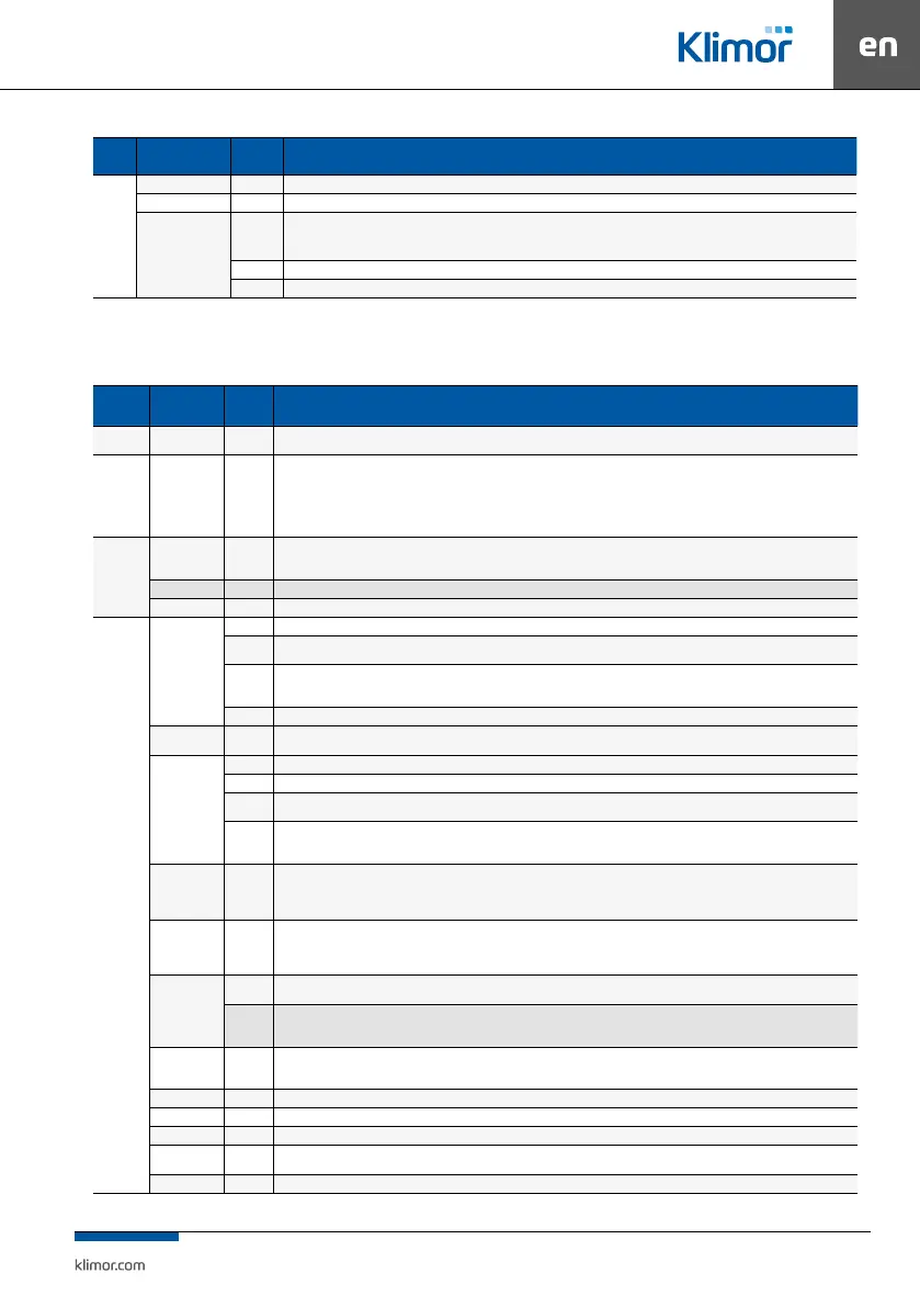
Group Name
Default
value
Description / Settings menu
Mixing
chamber
Min. fresh air 30% Min fresh air – dening min damper opening of the air supply/exhaust function while the system operates in the auto mode
Max. fresh air 100% Max fresh air – dening max. damper opening of the air supply/exhaust function while the system operates in the auto mode
Quick heating
Active
Quick heating – this functions enables quick heat up of the system to reach set temperature. When the quick heating mode is active and this is
necessary to activate it, the dampers block completely fresh air inow till the requested temperature is reached. This function is active only in
case of air supply-exhaust systems with recirculation.
5°C Tlim – requested temperature for quick heating function
2°C Temperature hysteresis – Tlim temperature hysteresis
9.4 Service menu
Access to these settings is password-protected (default: 1111).
Table no. 18 Service menu
Name Name
Default
value
Description / Service menu
Service
mode
- Active
Active – possible system set up, it is not possible to start the system, activated protection functions of selected system
Inactive – it is not possible to set up the system, the system can be switched on
Operation
mode
- o/on
o/on – active operation mode OFF/ON
o/1/2/3 – active operation mode OFF/Speed1/Speed2/Speed3
o/1/2/3/T – active operation mode OFF/Speed1/Speed2/Speed3/ Timer
o/1/2/3/S/T – active operation mode OFF/Speed1/Speed2/Speed3 / Standby / Timer
Note!!! Operation for settings on the TP4,3 and TP7 graphical touch panel menus is available in o/1/2/3/S/T mode, in other modes only the
simplied „saver” graphic screen invisible.
AHU type
Type SCS
SCS – air supply AHUs
SECS – air supply-exhaust AHUs
PRCS – air supply-exhaust AHUs with bypass-equipped cross-ow heat recovery
Application code 0 A setting of the code consistent with coding described in the point 4
Code consistency Correct Code consistency check, if not consistent it is not possible to start the system and the A_Code alarm message is displayed
The set up
Temperature
- Oset – the possibility to adjust the measuring points from temperature sensors
-
A_LowTemp – System operation locks function, when the fans operate too long at low air supply temperature.
Possibility to activate/deactivate the function, min. air supply temperature setting, low temperature alarm triggers delay setting.
Active
Air exhaust sensor:
Active – operation of the system with an air exhaust temperature sensor
Inactive – operation of the system without an air exhaust temperature sensor
20s Zmiana Tset – temperature change ramp (elimination of sudden change for stepless operation of temperature regulators)
Types of fan
inverters
Danfoss
Danfoss – choice of modbus RS485 control of Danfoss FC51 inverters
EBM – choice of modbus RS485 control of EBM fans
EBM address
1 Current address – address setting which is currently set at the EBM fan
1,2,3,4 Target address – address setting required for a particular EBM fan
No
Set address – uploading a new address to the currently connected EBM fan (after loading the settings turn o and turn on the power supply of
EBM fan, to active the new address!!!)
Ok
Status OK – uploading the setting completed successfully.
Uploading – the system is uploading the setting, in case of correct communication it takes about 2 seconds
Alarm – a problem occurred during uploading the setting (address error, communication error)
0÷10V air
supply
Inactive
Inactive – analog outputs conforms to functions described in the point 7.1
Aout1 – the 0÷10V signal is present on the Aout1 analog output of the air-supply fan
Aout2 – the 0÷10V signal is present on the Aout2 analog output of the air-supply fan
Aout3 – the 0÷10V signal is present on the Aout3 analog output of the air-supply fan
0÷10V air
exhaust
Inactive
Inactive – analog outputs conforms to functions described in the point 7.1
Aout1 – the 0÷10V signal is present on the Aout1 analog output of the air exhaust fan
Aout2 – the 0÷10V signal is present on the Aout2 analog output of the air exhaust fan
Aout3 – the 0÷10V signal is present on the Aout3 analog output of the air exhaust fan
Recovery
Work
mode
Work mode – possibility of heat or cool recovery activation
Inactive
Active – A_ColdRec frosting alarm visible in the alarm menu all the time during frosting,
Inactive – A_ColdRec frosting alarm not visible in the alarm menu, however a moment of triggering the frosting alarm is logged in the alarm history and the
frosting icon is present on the HMI screen when the heat recovery is frosted.
Electric heater 0-10VDC
Aout1 output function controlling the electric heater:
0-10VDC – stepless control of the heater output using the analog signal
PWM – stepless control of the heater output using the PWM 0/10VDC control
PWM period 10s PWM period – PWM period signal
PWM limit 100% PWM limit – Limit of the maximum electrical heater power with PWM controlled signal
Phe (%Psup) - Linear limit of the maximum power of the electric heater, depending on the control of the supply fans.
Work switch Inactive
The possibility to activate one of the relay outputs as a conrmation of work (make sure that the output is not used for other purposes in the
application).
Alarm swich Inactive The possibility to activate one of the relay outputs as a collective alarm ((make sure that the output is not used for other purposes in the application).