69
Alarms
Alarm
type
System response, action / Alarms list
A_Code Fading
Normal condition – no alarm, you can proceed to the system setup
and activation
Alarm condition – alarm triggered, the system is blocked till a correct
application code is entered (codes are provided in the point 3 of this
manual)
Response to the alarm condition: the system is blocked, once a correct
alarm code is set the alarm is reset automatically.
A_In_
Emul
Fading
Input emulation:
Normal condition – no alarm, no input in emulation mode
Alarm condition – at least one digital, analog or PT1000 input is in
emulation mode
Response to the alarm condition: the controller does not respond to
physical changes of the emulated input, the system operates with a
emulator value in the service menu.
A_Out-
Force
Fading
Forcing outputs:
Normal condition – no alarm, no output in the forcing mode
Alarm condition – at least one digital or analog output is in the forcing
mode
Response to the alarm condition: the system operates however the
forced output does not respond to the control algorithm, it is set with
the „Output forcing” menu in the service menu.
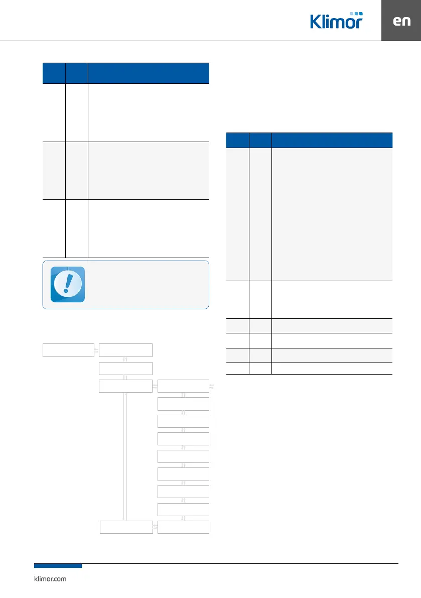
Fig. 6 Timer menu
9. CONTROLLER OPERATION
9.1 Main menu
In the Main menu and Settings menu there are shown
elements which cooperate only with the AHU type selec-
ted in the Service menu.
Table No. 16 Main menu
Name Default Description
System
con-
dition
Service
mode
Service mode – the system is being set up, it is not possible to
start the system, activated protection functions of selected heat/
cool exchangers
Stop – the system is stopped, dampers are closed, fans do not opera-
te, activated protection functions of the system
Stop-failure – the system is stopped, at least one blocking alarm is
triggered; check the alarm list, determine a failure source, once the
failure is eliminated reset the blocking alarm
Preliminary heat up – in case of low external temperature the
systems with water heater needs preliminary heat up
Heat up – in systems with water heater if the anti-frost thermostat
sends an alarm, the water heater heat up is initiated
Cool down – in systems with electrical heater and DX cooler or HPM/
CM module the fans are stopped after cool down time once the elec-
trical heater and/or DX cooler are stopped
Operation at level 1, 2 – correct operation in fan 1st or 2nd level
Main
menu
-
Selection of the AHU operation mode, requested temperature of
the master sensor, readout of temperatures and operation con-
ditions of fans and heat/cool exchangers, info about compressors’
operating condition, four-way valve operating condition, soleno-
id valve operating condition, low pressure gauge operating con-
dition and pressure value of pressure transducers.
Timer -
It enables programming of the timer. See point 9.2 Timer for
adetailed description.
Settings -
Parameters of the control system See point 9.3 Settings for ade-
tailed description.
Service
menu
- It enables set up of the fan system.
PL/EN/
- Selection of menu language (Polish/English).
9.2 Timer
The timer program options enable setting up a date
and time of the real time clock. When the operation
mode is set as “Timer” system control will be realized
according to stored programs. The timer program con
-
tains daily zones and exceptions.
A program contains two parameters:
Operation mode – available options: Stop, Speed1, Speed2,
Speed3, Standby(depending on the selected Mode in
the service Menu Speed 2, 3 and/or Standby may not
be available
Temperature setting – preset temperature.
Operation in the forcing or emulation mode
can lead to the AHU damage (fault of the user).
Changing in-puts/outputs in the forcing or em-
ulation mode can be performed only by quali-
ed personnel and this function can be carried
out only for testing or start up purposes.
Timer
SET DATE
FR 03- 05-11
SET TIME
21:57:00
WORK MODE MONDAY
MONDAYSET TEMP
FRIDAY
WEDNESDAY
SUNDAY
TUESDAY
SATURDAY
THURSDAY
EXEPTIONS