87
12. 3-PHASE DIAGRAMS FOR AN APPLICATION
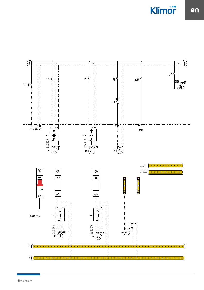
1. In the “2S” control cabinets designed for controlling air supply AHUs EVO-T 4100, 1200 and 9200 equipped with fan sec-
tions with single fans – power supply of EC fan or inverter of AC motors connected to the F1M1 fuse.
2. In the “4S” control cabinets designed for controlling air supply AHUs EVO-T 1200 and 9200 equipped with fan sections with
double fans – power supply of EC fan or inverters of AC motors connected to the F1M1 and F2M1 fuses.
Fig. 26 Power supply diagram for „2S” control cabinet, with single air supply, single air exhaust or double air supply only
Fig. 27 Components of control box for „2S” control cabinet, with single air supply, single air exhaust or double air supply only