84
AUTOMATION AND CONTROL SYSTEM FOR UNITS EVO-T; EVO-T COMPACT
OPERATION AND MAINTENANCE MANUAL
10.5 Communication RS485 Slave, Modbus RTU and connection method with the EBM motor
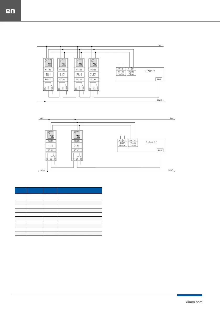
Fig. 20 Example for “EVO-T 4S” system, with double air supply, double air exhaust
Fig. 21. Example for “EVO-T 2S” system, with single air supply, single air exhaust.
Table no. 25 Connection of the EBM fan wires
Cable Connection Cable color Cable function
1,2 PE
yellow-
-green
Ground
3 N Blue Power supply – "0"
5 L Black Power supply – Phase
6 NC White 1 Motor condition relay – open, failure
7 COM White 2 Motor condition relay – open, failure
8 0-10V Yellow Analog input
10 RSB Brown RS485 MODBUS
11 RSA White RS 485 MODBUS
12 GND Blue "0" for control signal
13 +10V Red 10VDC 10mA output
Only 1, 2, 3, 5, 6, 7, 10, 11, 12 wires are connected to appropriate terminals at the control board.